Current Sensing

Delancy7

1 mW
Joined
Apr 3, 2024
Messages
18
Location
California
I've been using controllers to understand FOC motor control, and these small, cheap controllers typically implement motor phase current sensing as low-side shunts on two or three of the phases. This works, to an extent, but seems very noisy and not the best way to sense current, and is probably implemented on cheap controllers because of cost considerations.

I plan to create my own controller for test purposes and want to use a better method of motor phase current sensing. What's the best practice for motor current sensing in this application? This controller will be a one-off and cost won't be a consideration--I'd prefer a robust and accurate method as opposed to something cheap to implement.

The motors I'm using are small, and typical currents will be no more than 5-10 amps at 24v.
 
You can use this kind of FOC development board,
Thanks for the reply, but this doesn't answer my question. I'm not looking for a pre-made controller board, especially one that uses low-side shunts to sense current, like the one you linked to.

What I'm asking for is advice on how best to sense current in motor phases. I'm planning to make my own controller.
 
You only have two choices, either a probe or a shunt.
 
See Hall effect current sensors at Allegro micro.
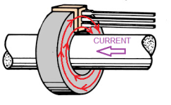
Thanks. I looked at those and they seem to be what I'm looking for. They seem to require the phase lines going to the motor to pass through the IC. What I was thinking of was a non-contact current sensor using a Hall effect sensor external the motor phase wires. To concentrate the magnetic field associated with current flow in the wires to the motor, I was considering using a ferrite toroid core with a notch cut into it to place the Hall sensor (I think these come in a TO-92 form factor). Run each motor phase line through the toroid enroute to the motor, with no physical contact between the phase wire and the Hall sensor. Has anyone tried this method?

Like this:
1714341184165.png
 
This works, to an extent, but seems very noisy and not the best way to sense current
?! Why do you think this is noisy? You just have to do it the right way. The timing is extremely important, to get proper reading. See this ST paper. Chapter 5 shows, how to do it right.


regards
stancecoke
 
Last edited:
?! Why do you think this is noisy? You just have to do it the right way. The timing is extremely important, to get proper reading. See this ST paper. Chapter 5 shows, how to do it right.
Why do I think it's noisy? Because I observe it on an oscilloscope.

I'm doing exactly what that paper you linked to describes. I'm using the fourth channel of TIM1 to trigger ADC conversion on the two ADCs that read the low-side shunt voltages at the proper time in the PWM cycle.

I think part of the issue I'm seeing is that my motors are small and the phase currents are low--much lower than what this controller supports, so the voltage drops across the shunts are low and I'm therefore not using the full range of the ADCs.

That paper is interesting in other ways however. One of the mysteries of the code I'm using is how it zeros the 4000 counts per turn quadrature encoder. The algorithm in the code seems to work, but I don't understand it fully. The ST paper says it should be done like this: "It consists of imposing a stator flux with a linearly increasing magnitude and a constant orientation." I think I know what they mean by linearly increasing magnitude, but I don't know what they mean by a constant orientation. Any hints?
 
at the proper time in the PWM cycle.
Are you variing the time with the duty cycle? Most people only measure at the middle of the cycle, that only works up to 70-80% duty cycle. Above that, the signal gets noisy. Then you have trigger the ADC conversion at a different time. Always make sure, that you read from the two phases with the lowest duty cycles.
Is your code public? I would like to take a look ;)

regards
stancecoke
 
Last edited:
Are you variing the time with the duty cycle? Most people only measure at the middle of the cycle, that only works up to 70-80% duty cycle. Above that, the signal gets noisy. Then you have trigger the ADC conversion at a different time. Always make sure, that you read from the two phases with the lowest duty cycles.
Is your code public? I would like to take a look

Yes. The code takes duty cycle into account when setting ADC trigger point and it uses the two phases with the lowest duty cycles.

The code is my Dad's. I'll have to ask him if I can share it when he gets back (he bought a sailboat in Massachusetts and is sailing it via the Panama canal to California and only has VHF radio, not HF or sat phone).
I've built inverters with the ring sensors, allegro chip sensors, low side shunts, phase shunts... I can confirm all work well with good design, and all work equally badly if you mess up the design of the board or inverter logic. I've successfully used low side shunts for boards running <10A and boards running 800A.

The lowest noise region to sample is if you choose the highest duty phase, work out the exact time it switches (this is trivially the highest CCR register) and count backwards from there by the ADC sampling time.
Below about 70% duty though, as stancecoke says, it's best to just sample dead center.

This is generally true for all forms of sensor.

The main reason to use inductive phase sensors is that it let's you get away with far far worse design of power stage, far noisier and with any amount of ground bounce which would wreck the signals from a low side shunt.
 
The lowest noise region to sample is if you choose the highest duty phase, work out the exact time it switches (this is trivially the highest CCR register) and count backwards from there by the ADC sampling time.
Below about 70% duty though, as stancecoke says, it's best to just sample dead center.
Just to clarify here: when you refer to highest duty cycle, are you referring to the duty cycle of the high-side MOSFET or the low-side MOSFET? This code sets up TIM1 with complementary outputs, so when the high-side MOSFET for a phase is on, the low-side MOSFET is off, and vice versa (with deadtime insertion, of course).

You say that to sample at the time of lowest noise, I should look for the CCR with the highest value and back off that by the ADC sampling time. The way the timer is set up, the higher the value in CCR, the shorter time the high-side MOSFET will be on, and the longest time the low-side MOSFET will be on. Is this the correct approach? What is the benefit of then starting the conversion earlier by subtracting the ADC sampling time?
Obviously you're looking to sample when the low side mos is conducting so if your code is written upside down you need to adjust the logic accordingly.
 
Obviously you're looking to sample when the low side mos is conducting so if your code is written upside down you need to adjust the logic accordingly.
Yes, I understand that. I'd still like to know the reason behind starting the ADC sampling before dead-center of the PWM cycle.
 
Yes, I understand that. I'd still like to know the reason behind starting the ADC sampling before dead-center of the PWM cycle.
After dead center. To minimize noise you want to allow the opamp as much time as possible to stabilize and for transients and noise to decay.
 
After dead center. To minimize noise you want to allow the opamp as much time as possible to stabilize and for transients and noise to decay.
That makes sense. When you said "work out the exact time it switches (this is trivially the highest CCR register) and count backwards from there by the ADC sampling time" that threw me off.
 
Back
Top