Double bms issue

maarkmohamed

100 W
Joined
Jan 10, 2019
Messages
114
Hello, would greatly appreciate help with my circuit that I have in mind. The objective of the circuit is to have two 72v batteries that are connected in series, both of which have a bms on them. Both bms will not be used for discharge and only for charging. Rather for discharge safety I have a dc contactor that I would like to be turned off if either of the bms triggers it to turn off. With this in mind I have attached a drawing of my current circuit. As mentioned there is two 72v batteries connected in series, then from each battery I take the negative from the bms and the positive and run it to a step down converter on both sides. From there I connected the step down converters in series so that i an left with one positive and one negative wire. The step down converter is set to 6v on each output. Therefore two of them in series makes 12v to turn on the contactor. If one bms turns off its not enough voltage to turn on the contactor. However the issue is, when I connected the 72v batteries in series, the step down converter capacitor blew up on the output side. From what I'm being told the reason for it blowing up is because the step down isn't isolated from input to output. That being said anyone have a good solution for this?1000008463.png Sorry for the long write up. I really appreciate the help.
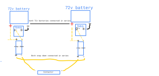
 
Keep in mind that a contactor that is already engaged doesn't take nearly as much current (or voltage) to keep it closed as it does to close it. So unless you've already tested the contactor under the conditions you're wanting to use, you could end up with a situation where charge starts, but then fails to disconnect when one BMS has shutdown.


Also, are these common-port BMS? So that P- is the same as C-? If not, some BMS disable P- during charge, so it wouldn't power your contactor.

I'd guess you are using the BMS FETs only to run the contactor / etc system, and that charging is actually connected directly to the cell block from the contactor? If you're actually using hte FETs to charge thru, then if your BMS are not designed to handle the full 72v+72v series voltage, you could end up with a FET failure that locks the charge port "on" permanently, so the BMS cannot stop a charge anymore, no matter what is wrong.


Regarding the proposed setup:


How about just using a contactor or relay on each BMS, with the contactors' NO contacts wired in series with each other and hte main contactor coil, so that:

As long as the BMS is enabled, then each BMS's charge output powers on it's own contactor coil. When either one shuts off charge for any reason, it opens it's NO contacts and disconnects the main contactor coil from any power, opening the charger connection.

As long as the contactor coils are both powered on, then boht contactors make a circuit to allow power to the main contactor (from whatever source you're using to power the contactor from (presumably if you're only using it during charge, this can be a separate AC-DC source from the charger but wired to the wall the same way as the charger, so you don't need any DC-DC's on the batteries or built into your vehicle for this, and you don't need two isolated DC-DCs).


All of the parts of this can be built into the charger setup itself, if you have enough pins in your charger port, so none of it has to be built into the vehicle or battery.
 
Last edited:
Amber appreciate the response although I am a bit confused with your answer and that might be just because I'm a visual learner. I will try to answer your points as best as I can. Firstly the bmss both are same port. So p- is used for both charge and discharge. As for testing the contactor with both bmss, when the 72v batteries are not connected in series and are separate I did test it and make sure that if one bms were to turn off then the contactor turns off. I didn't have any issues there only until I connected the batteries in series did the capacitor blow up on the step down. Regarding charging I didn't mention or draw out what I had planned for that. This I have not tested yet and you tell me if this would or wouldn't work. I was planning on charging both batteries simultaneously with one 72v charger. The charge connection does not go through the contactor and instead goes directly through p- on both bms and the main positive of both batteries. If I need to run two different 72v chargers for each battery that's fine, but i was thinking but haven't tested yet if charging both batteries simultaneously when one of the bms gets full it would close and not allow for any charge, but since the charger detects the other battery not full it will continue until the other is full then turn off. Would this work or am I misunderstanding something? Essentially charging both in parallel. As for the separate relay for for each bms connected in series then connected to the main contactor, I'm still having a bit trouble understanding that wiring again maybe just because I'm a visual learner. I'm familiar with automotive relays and most of them that you can find online have a operating voltage of 12-24v and we would need something over 80v for each bms of you would like to share a link of one you had in mind. Side note I have a small test rig which I made to test everything just to be on the safe side before trying to do all this with big batteries and so on just to test the theory.

Thanks again
 
Keep in mind that a contactor that is already engaged doesn't take nearly as much current (or voltage) to keep it closed as it does to close it. So unless you've already tested the contactor under the conditions you're wanting to use, you could end up with a situation where charge starts, but then fails to disconnect when one BMS has shutdown.


Also, are these common-port BMS? So that P- is the same as C-? If not, some BMS disable P- during charge, so it wouldn't power your contactor.

I'd guess you are using the BMS FETs only to run the contactor / etc system, and that charging is actually connected directly to the cell block from the contactor? If you're actually using hte FETs to charge thru, then if your BMS are not designed to handle the full 72v+72v series voltage, you could end up with a FET failure that locks the charge port "on" permanently, so the BMS cannot stop a charge anymore, no matter what is wrong.


Regarding the proposed setup:


How about just using a contactor or relay on each BMS, with the contactors' NO contacts wired in series with each other and hte main contactor coil, so that:

As long as the BMS is enabled, then each BMS's charge output powers on it's own contactor coil. When either one shuts off charge for any reason, it opens it's NO contacts and disconnects the main contactor coil from any power, opening the charger connection.

As long as the contactor coils are both powered on, then boht contactors make a circuit to allow power to the main contactor (from whatever source you're using to power the contactor from (presumably if you're only using it during charge, this can be a separate AC-DC source from the charger but wired to the wall the same way as the charger, so you don't need any DC-DC's on the batteries or built into your vehicle for this, and you don't need two isolated DC-DCs).


All of the parts of this can be built into the charger setup itself, if you have enough pins in your charger port, so none of it has to be built into the vehicle or battery.
On a side note someone shared this with me. A isolated step down relay. Only thing I see is that it says max voltage 75v not sure if 84v would be a problem.
 
Ok, lets look at it this way.

It can *ONLY* survive a fall from 75 feet. Anything more, and it not promising anything best of luck.

"I wonder if I can toss it off everest"

If the *MAXIMUM* of something, it is a set hard number that is cushioned by 5-25% depending a lot of details. Will it survice 76v absolutely never seen a circuit that was that tight in the wiggles.

WIll it survive 80... hmm, that is like more than 1 extra yeah?

Might work, might go bang and wooooh Magic smoke, it's your kit at the end of the day.
Lol. I'm speaking to several people regarding the isolated step down I listed and they are saying it still won't work because the contactor coil requires close to 3 amps to close (turn on) and the step down is only 1w if I'm not mistaken.
 
I have an inrush inhibitor that I am switching in and out with a remote control based unit. It kicks open the bridging circuit, then a timer runs to allow things to equalise and then triggers the relay for the standard connection to open, then another timer just because I like waiting, it is like 5s and it de-shunts the circuit so you are not busily turning electrons into heat.

This remote has it's own battery unit, you can totally use the mechanical switch it just lives up to being a device installed by a sparkty.
Thanks for sharing this. I'm really looking for something compact in size similar to the size of a automotive relay only because I would have to fit it in to the battery box, and in this case two of them
 
I have tried 12v auto relays, they smell unusually bad when the light up, and the smoke while stinky is thin.. Total disapoint, 1/9 would not re-explode
 
Keep in mind that a contactor that is already engaged doesn't take nearly as much current (or voltage) to keep it closed as it does to close it. So unless you've already tested the contactor under the conditions you're wanting to use, you could end up with a situation where charge starts, but then fails to disconnect when one BMS has shutdown.


Also, are these common-port BMS? So that P- is the same as C-? If not, some BMS disable P- during charge, so it wouldn't power your contactor.

I'd guess you are using the BMS FETs only to run the contactor / etc system, and that charging is actually connected directly to the cell block from the contactor? If you're actually using hte FETs to charge thru, then if your BMS are not designed to handle the full 72v+72v series voltage, you could end up with a FET failure that locks the charge port "on" permanently, so the BMS cannot stop a charge anymore, no matter what is wrong.


Regarding the proposed setup:


How about just using a contactor or relay on each BMS, with the contactors' NO contacts wired in series with each other and hte main contactor coil, so that:

As long as the BMS is enabled, then each BMS's charge output powers on it's own contactor coil. When either one shuts off charge for any reason, it opens it's NO contacts and disconnects the main contactor coil from any power, opening the charger connection.

As long as the contactor coils are both powered on, then boht contactors make a circuit to allow power to the main contactor (from whatever source you're using to power the contactor from (presumably if you're only using it during charge, this can be a separate AC-DC source from the charger but wired to the wall the same way as the charger, so you don't need any DC-DC's on the batteries or built into your vehicle for this, and you don't need two isolated DC-DCs).


All of the parts of this can be built into the charger setup itself, if you have enough pins in your charger port, so none of it has to be built into the vehicle or battery.
Amber do you mind sharing with me which relays you had in mind for each bms?
 
That's something you'd have to determine based on your voltages, currents, etc. You would need relays that have a coil voltage appropriate to whatever you're using to switch them on, and contact voltage and current capabilities that are at least as good (preferably significantly higher) than your system max voltage and the worst-case current flow they'd ever see.

You can go to places like Mouser, or Digikey, etc., and see there is a huge selection of relays, contactors, etc out there.


I won't promise to sketch a circuit diagram of my wiring descriptoin but if I have a chance I'll try to post one up.
 
Last edited:
Regarding charging I didn't mention or draw out what I had planned for that.

The wording of your post sounded like you were *only* talking about charging, and specifically not discharging? If you need this setup for discharging, it'll be different than what I previously described.


This I have not tested yet and you tell me if this would or wouldn't work. I was planning on charging both batteries simultaneously with one 72v charger. The charge connection does not go through the contactor and instead goes directly through p- on both bms and the main positive of both batteries. If I need to run two different 72v chargers for each battery that's fine, but i was thinking but haven't tested yet if charging both batteries simultaneously when one of the bms gets full it would close and not allow for any charge, but since the charger detects the other battery not full it will continue until the other is full then turn off. Would this work or am I misunderstanding something? Essentially charging both in parallel.

You cannot charge them in parallel if they are wired in series, that will short the "bottom" one out and make a nice toasty fire. :(

You *can* charge them with completely independent *isolated* chargers, however, and then they will charge as if they were not connected to each other at all.

If the chargers are not isolated, you are still shorting across the "bottom" pack....so make sure you test the chargers, without power connected to them on either end, with a multimeter to see if there is *any* electrical connection from *any* output wire back to *any* input wire, or the case, etc. If there is, then they're not isolated, and cannot be connected at the same time to a seriesed set of batteries. (the case only matters if they are touching each other, or any electrical connection goes to the casing or anything the casing is mounted to, etc).
 
The wording of your post sounded like you were *only* talking about charging, and specifically not discharging? If you need this setup for discharging, it'll be different than what I previously described.


You cannot charge them in parallel if they are wired in series, that will short the "bottom" one out and make a nice toasty fire. :(

You *can* charge them with completely independent *isolated* chargers, however, and then they will charge as if they were not connected to each other at all.

If the chargers are not isolated, you are still shorting across the "bottom" pack....so make sure you test the chargers, without power connected to them on either end, with a multimeter to see if there is *any* electrical connection from *any* output wire back to *any* input wire, or the case, etc. If there is, then they're not isolated, and cannot be connected at the same time to a seriesed set of batteries. (the case only matters if they are touching each other, or any electrical connection goes to the casing or anything the casing is mounted to, etc).
I will not be using the bmss for discharging, only using there p- cable for signaling on and off the contactor and for charging the pack. So I will be bypassing the discharge on the bms. I will take note of the charger isolation and make sure to check like you mentioned. And I figured it would need two separate individual charges to charge both batteries when connected in series.
 
Back
Top