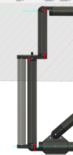
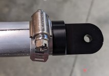
Another thought I had overnight - why not just add a key to the connector faces? i.e. mill a slot, say 3mm deep and 6mm wide, into the faces of the relevant connectors.
I do believe that this same "keying" function is served by that DragonPlate connector style that you already discovered, with that jagged circular pattern in it. That plus some LocTite and you're way past what I was dumbly attempting by just over-tightening the screw until I pulled out the threaded insert. (What a meathead.)
Like you say, the solution to that uncertainty is to test it out! It definitely sounds like there's a consensus that I should make a model/mockup/prototype of this before doing any bonding. I guess I'm a little reluctant because I'm excited to get the final product built and in service, but a mockup will definitely reduce risk of failure, so okaaayyyy.
Do your thing your way, for sure. I'm just "projecting" here. If you have confidence that your design is good, then what the hell. But if you find yourself just not
quite up and doing it, then that would suggest some low-dollar experimentation and fooling around is called for.
but gave up and forked out the money for some LightLeaf panels. They're much better than anything I could build. I considered using Solbian 118Q panels (same 6x6 SunPower cell arrangement as my LightLeaf panels) with aluminium strips under each row of cells and an aluminium extrusion frame supporting the whole thing, but it was going to be heavier and just as costly as the LightLeaf panels.
Hey thank you for the hookup on these LightLeaf's. These are very nice. Some numbers:
LightLeaf 150W 52"x23":
~20 nameplate watts/pound
Custom Marine Products "Semi-Rigid - Monocrystaline" 170W 48"x26":
~11 nameplate watts/pound
Custom Marine Products "Semi-Rigid - Monocrystaline - Light" 170W 48"x26":
~13 nameplate watts/pound
Well freaking well! How you like
that? What I'm "seeing" here is that these nerdy Canucks are taking the kind of super-fancy composites work that
@solarEbike did by hand, and have applied some tooling and automation to it so as to then sell them to people for less than $10,000 per panel. And good for them.
(It's that armored
edge around the perimeter of each LightLeaf panel that's really getting my attention.)
Yo
@solarEbike: What do you say to these numbers?
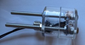
@solarEbike has done a lot of modelling work to compare automatic single-axis sun tracking vs manual tracking (i.e. stop the bike and rotate panels yourself occasionally) vs fixed horizontal panels. Strong conclusion was that the equipment needed for automatic single-axis tracking adds just as much weight as the equivalent number of extra solar cells would add (i.e. the number of cells needed to gain the same benefit that the tracking gains), yet automatic tracking is far more complex. So just adding more panel and forgetting about automated tracking is a very reasonable decision. I'm only doing tracking to reduce trailer size (for transport) and because it's a cool toy (yes, I'm a nerd).
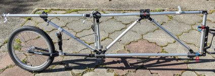
Well it's like this. 3x 48"x26" panels come together to make something 12 feet long x ~2.2 feet wide, which given turning circles and the width of my handlebars, is about the biggest rectangle of anything that I'm believing I can cram/drag/cajole through the physical world.
For goofing around town, the trailer would have to come off, no doubt.
So since that's already maxxing out panel size, any
more power would have to come from tilting it
also. But just ~20% more? Sheesh man that's not a lot for all the work it would take. Whether I'm doing light sensing like
@solarEbike, or "just" calculating the optimum tilt angle from GPS position, compass heading and time of day (easy stuff to type into a web forum, but surely still hard to pull off IRL), yeeks man, do I
really believe in my own engineering
that much?
Fwiw, 3x 170W 48"x26" panels will result in a very large trailer - even bigger than my "Mark 1" trailer. It'll be a pain around town, but no problem on highway shoulders. 510W is a lot - you'll have to cover some serious miles per day (or cruise at high speed) to use all of that. I'd suggest trying 2x 170W first (i.e. design your truss so it could be extended with another panel later?) to see if that's sufficient.
Well for now I'm just playing "train set" in my head, and gunning for an attention-seeking round-the-world show-off trip, so it "has to be" all 3x 48"-long panels, if only for show. (The only way I can even conceive of shipping this across an ocean would be to rent out a 20-foot shipping container, and wait for it on the other side.)
See I'm not thinking about watts per se, but watt-hours per day. (3) x (170 watts nameplate) x (3.5 watt-hours per nameplate watt per day) = 1800 watt-hours/day. 1800 watt-hours/day / (40 watt-hours per mile) = ~45 miles/day for this big bulky monstrosity = ~70 km/day, if I'm not able to pedal much, and I'm getting ready to be old here.
Mind you I'm
also thinking of using 3x (36V x 24 Amp-hour) batteries = 2600 watt hours of battery, or 1.5 days of solar, or an additional ~50-60 miles if I start the day charged up. (30 freaking pounds of batteries, man.)
100 miles/day sounds like a lot, but it's not really. There will be some stretches of South America, and Africa, where I'll really
want that 100 miles.
So you can see where I'm at head-space-wise. I'm trying to go Battlestar Galactica with this thing. Mid-drive through a Rohloff so I can still struggle up 15%-17% mountains without burning stuff out, etc. That's the mental game I'm playing.
If the weight reduction effort doesn't solve the problem fully, I'll add a second motor. It just seems like an ugly solution though, if you know what I mean? Throwing power at the problem instead of improving energy efficiency.
Well shucks man, whatever floats your boat. I'm just curious as to what would happen if you started with the Mark 1 trailer that you already have
right now, and "simply" bulked-up the bike with a front motor (and/or powered the trailer wheels?) and a bigger battery.
The devil on your shoulder asks:
Could it actually be shown that
that would be functionally superior to what you're trying for here with the Mark 2?


")