Switchable voltage divider instead of throttle.

zacksc

100 W
Joined
Jan 26, 2019
Messages
154
Location
California, Bay Area, USA
For a sort of stealthy, discrete project, I am thinking I would like to use a switchable voltage divider in place of a throttle. Something where I could switch through 4 or 5 levels of assist using a small solid state voltage divider connected to the motor controller via the three throttle wires*. I’d like it to be pretty small and something I can control by a push switch which cycles it through 4 or 5 voltages at the output (by changing the voltage division). Is that difficult to do? I don’t mind spending a bit of cash. How could one do something like this using a solid state approach? Could the controlling switch possibly be remote, like a key fob? Any help will be very much appreciated!

* The controller would be either a Grinfineon 20 amp or a Phaserunner. I think for either one the wires intended for the throttle include a 5 volt nominal, a zero volt and an output (signal) wire at some in between voltage. I am thinking this would be low current, e.g., about a milliamp.
 
there's a project already on es that does this, from several years ago, using a little mcu.
https://endless-sphere.com/forums/viewtopic.php?t=47524

there's another one somewhere I can't find atm, if i do i'll post it up.

oh, also, the old crystalyte cruise control units will do this, without any work other than wiring one up. ;)
https://www.google.com/search?q=crystalyte+cruise+control (most of the results are here on es)
 
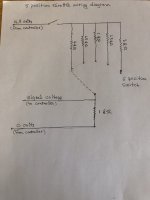
Thanks Amberwolf. What about something like this using a 5 position switch to get 4 preset levels of assist? What would be a good way to actually make something like this? Does it seem like it would work okay?
Thanks,
Zack
 
Would something like that maybe work with a phaserunner or grinfineon controller? Could that be done in a solid state kind of way, or would it be preferable to just use a mechanical switch? Is there a better way to divide voltage?
 
the only potential issue about a switched resistor set is if there is enough time between positions for voltage to fall far enough to trigger a controller reset or lockout, if it's the type of controller that does that. (you can test this by using a regular throttle, and putting a switch in the signal wire, so that when you turn the switch off and then back on, with the throttle at a partial-on setting, the controller either first stops and then restarts at the level it was at (if you don't change throttle), or it stops and doesn't restart. if it doesn't restart, then you could have that problem with the switched-resistor version).


otherwise, it doesn't really matter how you derive the voltage that becomes the throttle signal. and doesn't matter what controller it is. if it uses a simple single-voltage input on it's single throttle signal line, it'll work with whatever voltage source you use that's within the correct range for that controller's input.


if you want the "simplest" way to have button you can push to change throttle, that crystalyte cruise control is it, cuz you just have to wire it up. (and it's also designed to have a throttle hooked up at the same time, if you like, which would take a little bit of design work to get done otherwise). the disadvantage is the increments are small (either 64 or 128, i forget which) when pushing the + or - buttons, so it can take quite few presses to get where you want. but you do have more control because of that.

the mcu-based project(s) i linked would be the next best non-resistive way to do it, because you can change the code (if you know how to do that; i don't) to have whatever specific levels you like on each button press.


the simplest passive-component version is basically your rotary switch, as drawn, with whatever values of resistor that give you the throttle signal voltages you're after.


there are even digipots, like the ones maxim makes, which you can use a pair of switches to increment or decrement the amount of resistance they present at teh outputs. should be easy enough to make the right circuitry to generate a certain number of pulses for each switc h press to change the resistance by a fairly large amount each time, so you only have a handful of throttle levels from off to full.


it's probably even possible to use the cycle analyst's digiaux function to output just a few specific throttle levels (if you only need three, even the presets might work). i don't know precisely how to set that up in it's menus, but we can look into it if you already have a ca v3.
 
Thanks. Is there a solid-state version of a rotary switch such that I could operate it from a small button mounted on my handlebars connected buy two small wires to the rotary switch/voltage divider?
 
My goal is to make a really minimal set up with just 2 Ligos, a phaserunner and the voltage divider throttle replacement. I think if there were a solid-state version of a rotary switch such that I could operate it from a small button mounted on my handlebars connected by two small wires to the rotary switch/voltage divider, that would be pretty cool. Anybody have a suggestion for if/where I can buy something like that?
 
So a single button, so that if you're in the middle power setting and want to go lower, you have to cycle through the higher throttle settings to get to the lower setting? Or are you thinking of an up and down button?
 
zacksc said:
Thanks. Is there a solid-state version of a rotary switch such that I could operate it from a small button mounted on my handlebars connected buy two small wires to the rotary switch/voltage divider?
that's what the projects i already posted about do, effectively (give you remote button control of preset throttle levels).

they don't use a rotary switch, because a solid state version of one isn't a rotary switch anymore (doesn't need to be--the only reason for a rotary switch is if you need it to rotate, to spin, because what is controlling the switch must rotate and thus rotate the switch. otherwise it can be any form of switch). because it doesn't need to be an actual switch at that point, just something that outputs the levels you want, anything already described will do what you're after.

have you looked at any of the projects or devices mentioned so far?

the maxim digipots, with suitable electronics to create large enough "steps", are one of the simplest / smallest ways to achieve this/

if you really want a rotary switch to do this, but remotely, you can setup a small motor that then drives a rotary switch via gearing, like an rc servo. then use the buttons on the handlebars (up and down) to drive the motor as long as you hold the button. as the motor is driven it changes switch positions until it reaches the last one. you just let go of the button to stop changing positions and thus throttle settings. the problem with this is that you must keep fiddling with the buttons to get the motor to stop "on" a switch position, and not between positions. to fix that you need extra electronics that send specific-length pulses to the motor to make it run only just long enough to go from one postion to another, and never get stuck between them. an mcu could be programmed to do this, or you could use a 555 timer circuit, etc. (but if you're building electronics anyway, the other projects would be "better" than this).

or use the motor to drive a potentiometer, for continuously variable throttle, so you don't have to fiddle with the buttons over and over to get it to actually be "on" a switch position, without added electronics.

but the other projects already mentioned will be more reliable and easier to control from the buttons, and probably smaller.

if you really don't want to do any of those, there are electronic switches, too, but you'll have to design and build control electronics for those that can be operated from the button to increment/decrement which switch is on, and ensure all the others are off. the easiest way to do this is with an mcu, but if you're using one of those you might as well go with an existing design like the other projects.


note that however you do this, you probably want to use two buttons, up and down, rather than a single one, so you don't have to cycle thru the wrong direction of throttle amount to get what you want at that moment.

or if you must have a single button, you need to add electronics to the system that suppress all throttle output completely until you have not been pressing the button for a specific amount of time (say, a full second).

or you will need to use the ebrake lever (assuming you're not using regen) to disable the motor until you're done changing levels.

otherwise, you may suddenly end up with more power than you want, and cause you a problem, under various conditions.
 
E-HP said:
So a single button, so that if you're in the middle power setting and want to go lower, you have to cycle through the higher throttle settings to get to the lower setting? Or are you thinking of an up and down button?
Yes, maybe an up and down. Some very small discrete buttons.
 
amberwolf said:
the maxim digipots, with suitable electronics to create large enough "steps", are one of the simplest / smallest ways to achieve this/
Maxim digipot sounds good. Where can I buy that in small quantities?
What about an indented potentiometer with just a dozen or less detents? Where could I buy that?
 
zacksc said:
Maxim digipot sounds good. Where can I buy that in small quantities?
What about an indented potentiometer with just a dozen or less detents? Where could I buy that?
digikey, mouser, farnell, etc. any electronics distributor should have them, and they typically have online help to get you the right part for your application too. :)
 
Back
Top