Wiring tail light with blinkers to a 1T4 cable - need help figuring out the wiring.

Joined
Dec 2, 2023
Messages
14
Location
Toronto
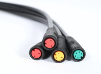
Got myself a first ebike - an inexpensive 48V 26"x4" fat ebike with S830 display. It doesn't have a tail light. I want to add a working tail light with brake light and blinkers, as inexpensively as possible, and without voiding the warranty (means no cutting and splicing). But I'm puzzled by the wiring, need to figure it out so I don't short and burn anything... At the steering bar, my wiring harless looks like this. I understand this is called 1T4 wiring harness, correct? Only my harness has 2 yellows instead of one. The left yellow is wired to headlight and horn switch, which shorts one of the 2 pins with the common pin on the second yellow connector. 2 Reds are brakes, right Yellow is the throttle, and Green is the display.
1701563372511.png

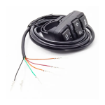
My plan is to buy Y-cables (splitters) to tap into +48V voltage, ground and brakes, cut one of their ends and wire this switch from Ali Express:
1701564101367.png
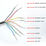
It has a really Chingrish pinout, someone has posted than red,yellow and brown need to be shorted, which makes sense if they are +48V:
1701564152588.png
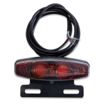
And this is the tail light with blinkers:
1701564264418.png
Both switch and tail light say "48V" in the description, so I hope it whould work.

- I can't find any pinouts for this! I don't even know where the ground is.
- How would I do the break lights? What voltage is there that brake levers short? Can't even measure without knowing what pin the ground is... Can I wire them directly? Or do I need 5V relays to connect +48V to the break light?
- I suppose the Green connector to display has +48V and ground that I can tap, and feed to tail light, blinkers and break, correct? Which pins though?

I'd appreciate any advice!
 
Most of the controllers / displays that support lights have a very tiny electronic switch in them that can barely handle any current at all, and can fail even when used within the limits they're "designed" for.

I recommend not using any of the controller or display wiring or connections for any of the lighting, and just connect the lighting and control switch directly to the battery supply connections, or to whatever keyswitch or power switch you have, if any.

Then you don't have to worry about frying your controller or display by overloading it, or accidentally miswiring anything. And something going wrong with the controller or display won't stop your lights from working, leaving you not only without assist but also without any lighting for visibility or communication of intent to other road users.

It means you need separate wiring for all of the lighting stuff, including the handlebar control, but the safety of the separation of the systems is worth the extra wiring and work.


Unless you are using regen braking on your system via the brake levers, you don't need to use them on the controller at all, and can disconnect them from the controller and use them exclusively for lighting control.

The levers normally just short the controller's brake input signal to ground. There is an internal 5v on a pullup resistor inside the controller on it.


If you require the levers on the controller for some reason, you can get a very-low-current (5-10mA range) 5v-coil relay (with 60v+ rated N.O. contacts) that you can wire the coil from controller 5v (from the throttle connector) to one side of the brake lever. Other side of the lever to controller ground. in series with the brake lever's 5v supply wire. The lever ground remains conected to controller ground. Brake signal to controller remains on the coil-connected side of the relay. The brake light ground connects to the NO contact, and the common connects to battery ground. When you pull the lever, it grounds the controller ebraek input, turning it on directly, and engages the relay coil that closes the contacts and turns on the brake light.

*or*

A single 50-60v coil (low current is better, but doesn't require tiny tiny low-mA currents like the 5v would) relay with 5v+ rated N.O. contacts taht you wire the coil in series with the levers but the levers don't connnect to the controller at all--they only connect to one side of the coil, and ground. Then battery postive connects to the other side of the coil. The brake light ground connects to the coil/lever connection. The NO contact goes to the controller ebrake input, and the common contact goes to controller ground. When you pull the lever, it grounds the brake light, turning it on directly, and engages the relay coil that closes the contacts and turns on the controller ebraek input.


The wiring info above assumes the brake/turn module supplies power to the ligths and that each of hte signals is grounded to activate the lights. If instead the module supplies ground to the lights and each of the signals is powered to activate the lights, the wiring has to be different.

Can you open the module to trace where the wires go? That's the "safest" option. If not, then you'll have to apply power to the lights to find out which wire is which. If you have a 12v battery or power supply, and a mostly dark room, you can test to see which wires do what, without as much risk of blowing it up as with a 48v supply. It's likely that the unit is powered via the red (+) and black (-, ground) wires, so connect htem to the battery. Then touch each of the other wires to the battery - one at a time to see which lights come on. If none do, try them to b+. If none come on, then either the black and red don't power the unit, and you can either start guessing at other combinations (risking damage), or you can try a 48v source instead of 12v and retry the original tests.


The handlebar light control is probably wired wtih "turn to the public" as common for the left/right turn signals, so that whenever you flip that switch from center (off) to one side or the other, it connects that side to the "tttp" common wire. If the turn signals are turned on by grounding them, you wire tttp to ground. If they're turned on by b+, you wire tttp to b+.

The "trumpet" is the horn switch. If you don't have a horn you can use it as a momentary switch for anything that's useful for.


What "negative electrode" hooks to, I don't know. Best guess is it goes to B- and is used for the headlight common, so that the two headlight wires are for high and low beam. The headlight itself would then be wired from B+ on it's positive side, and then if it has a high and low beam they'd go to the two headlight wires. If there's only one, you can just connect to either one, and then the other would be off.

If the HL wires are just a single switch not connected to anything else, then they just go between either B+ and the headlight, or b- and the HL, doesn't matter.

You can use a multimeter on continuity or 200ohms setting to test which wires go to which switch, and what happens in each switch position.
 
Most of the controllers / displays that support lights have a very tiny electronic switch in them that can barely handle any current at all, and can fail even when used within the limits they're "designed" for.
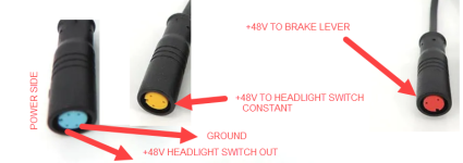
Thanks a lot for the detailed reply. I managed to find thin enough wires to get the multimeter connected to the cables. The results are encouraging but a bit surprising. First, the cables provide +48 current to the rather powerful headlight with 4 high-power LEDs, so I think they should handle some brake/turn LEDs.

I found a ground wire in the blue cable, but +48V is connected by a lights switch. So I can get the ground from the blue cable.

The yellow light switch cable has no ground, but has a constant +48V supply that the switch shorts to the headlight and the horn via the blue cable. So +48 can be had from the yellow cable.

What is surprising that using the ground from the blue cable, and a brake wire from the red cable, I measured +48V, not +5V as I expected. So it looks like I can wire the brake light directly from that, without the 5V relay switch as you suggested. It's a bit strange that the brake has +48V and not 5V as most schematics show, but that's what it shows. I still don't have the pinout for my bike specifically. I'll only use the right brake lever, because left is only used together with right anyway. I don't want to disconnect brakes from the controller, because they cut off the power from the motor, which is very handy even in my limited testing so far. I don't think it's safe to have a possibility of braking hard while the motor still tries to accelerate.

Basically I found this:
1701630094598.png

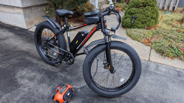
The bike looks like this, the battery is sealed and removable, and I think it has a controller inside as well, because there's nowhere else it could fit. So the only way to get to the ground and voltage is from one of the wire connectors at the handlebar. There's the thick one back near the motor, but it's a large many-pins-of-varying-thicknesses kind of a connector that I don't want to bother with. Even if I could find a splitter for it, adding more connectors on the way to the motor adds resistance and points of failure, which is not a good idea.

1701630118899.png

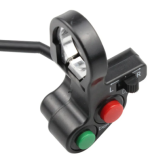
So what I think now is that I can get 3 splitter Y cables (blue, yellow and red) and a simple and more ergonomic swithc (without internal LEDs to complicate wiring):
1701630233410.png
And wire the lights that way. I don't see any other way... It's an unknown if I won't overload the controller, but hopefully if it can handle the headlight, it should be able to handle a few more low-power LEDs...
 
Don’t bank on the controller lights output being capable of managing more than one led light.

If you have front, brake, tail and indicator lights it is entirely possible that you will blow the lighting circuit in your controller.

There are several threads on Endless Sphere showing blown up components due to overloading the lighting circuit in the controller.

Also those switches are designed to switch relays to power the lights rather than being wired directly.
 
Got myself a first ebike - an inexpensive 48V 26"x4" fat ebike with S830 display. It doesn't have a tail light. I want to add a working tail light with brake light and blinkers, as inexpensively as possible, and without voiding the warranty (means no cutting and splicing). But I'm puzzled by the wiring, need to figure it out so I don't short and burn anything... At the steering bar, my wiring harless looks like this. I understand this is called 1T4 wiring harness, correct? Only my harness has 2 yellows instead of one. The left yellow is wired to headlight and horn switch, which shorts one of the 2 pins with the common pin on the second yellow connector. 2 Reds are brakes, right Yellow is the throttle, and Green is the display.

View attachment 343666

My plan is to buy Y-cables (splitters) to tap into +48V voltage, ground and brakes, cut one of their ends and wire this switch from Ali Express:
View attachment 343667
It has a really Chingrish pinout, someone has posted than red,yellow and brown need to be shorted, which makes sense if they are +48V:
View attachment 343668
And this is the tail light with blinkers:
View attachment 343669
Both switch and tail light say "48V" in the description, so I hope it whould work.

- I can't find any pinouts for this! I don't even know where the ground is.
- How would I do the break lights? What voltage is there that brake levers short? Can't even measure without knowing what pin the ground is... Can I wire them directly? Or do I need 5V relays to connect +48V to the break light?
- I suppose the Green connector to display has +48V and ground that I can tap, and feed to tail light, blinkers and break, correct? Which pins though?

I'd appreciate any advice!
It’s the white wire (headlight input) that has to be connected to 48 volts. If you connect the yellow wire (headlight output) to 48 volts then the blue light will be on all of the time Instead of only coming on when you press the button.
 
You also may need to fit a blocking diode to prevent the headlight illuminating every time the brake light comes on.
 
Back
Top