Im attempting to modify a cheap YK31A 24v 500W DC speed controller for use with 60v (or more) on a larger DC motor. I believe I have a handle on the necessary tasks:
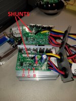
Here is the PCB in question:

Tentative Plan
1) Beef up the traces: Batt->FET->Motor
I will add heavy solder + overlaid copper wire to increase the current carrying capability of the traces.
2) Upgrade Caps
I've soldered in a single 180v 820uF cap in place of the original pair of 470uF 50v caps.
3) Modify resistor values in the resistor divider to adjust the LVC to 3.0v per cell.
I think i've located the resistor divider based on the voltage measurements, see image. I plan on adjusting the resistor value on the VCC side of the divider until I get 2.6v when VCC is at the cutoff voltage.

4) Upgrade FETs
I will replace the 2 stock FET(s) with IRFB7730s & add an additional FET into the unpopulated spot on the board. (the 36v 800W version uses the same board and has a FET there)
5) Decrease the shunt resistance - Add copper wire wrap + solder to reduce the resistance of the shunt.
Outstanding Questions
A) - Will a IRFB7730 be a suitable upgrade for the stock FETs (RU6888R)?]
The IRFB7730 has lower Rds(on) and can handle more watts overall. What other FET characteristics are important in this application?
Datasheet Links:
http://ruichips.com/uploads/file/20200819/20200819171503922.pdf
https://www.infineon.com/cms/en/product/power/mosfet/12v-300v-n-channel-power-mosfet/irfb7730/
B) - I do not see a current shunt anywhere in this circuit. Is it possible there is no current limiting in this circuit? How can i modify the current limiting? or do I need to?
Any input or direction on the two questions / LVC mod plans would be truly appreciated! Thanks!
Here is the PCB in question:
Tentative Plan
1) Beef up the traces: Batt->FET->Motor
I will add heavy solder + overlaid copper wire to increase the current carrying capability of the traces.
2) Upgrade Caps
I've soldered in a single 180v 820uF cap in place of the original pair of 470uF 50v caps.
3) Modify resistor values in the resistor divider to adjust the LVC to 3.0v per cell.
I think i've located the resistor divider based on the voltage measurements, see image. I plan on adjusting the resistor value on the VCC side of the divider until I get 2.6v when VCC is at the cutoff voltage.
4) Upgrade FETs
I will replace the 2 stock FET(s) with IRFB7730s & add an additional FET into the unpopulated spot on the board. (the 36v 800W version uses the same board and has a FET there)
5) Decrease the shunt resistance - Add copper wire wrap + solder to reduce the resistance of the shunt.
Outstanding Questions
A) - Will a IRFB7730 be a suitable upgrade for the stock FETs (RU6888R)?]
The IRFB7730 has lower Rds(on) and can handle more watts overall. What other FET characteristics are important in this application?
Datasheet Links:
http://ruichips.com/uploads/file/20200819/20200819171503922.pdf
https://www.infineon.com/cms/en/product/power/mosfet/12v-300v-n-channel-power-mosfet/irfb7730/
B) - I do not see a current shunt anywhere in this circuit. Is it possible there is no current limiting in this circuit? How can i modify the current limiting? or do I need to?
Any input or direction on the two questions / LVC mod plans would be truly appreciated! Thanks!