DaTree
1 mW
I have a few questions.
if i have a 48v controller, can i use a 54.6v battery?
what are the bare minimum components required for an ebike?
motor, controller, battery, accelerator, and bike?
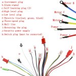
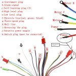
are there any ways to test controllers?
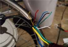
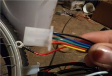
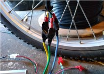
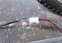
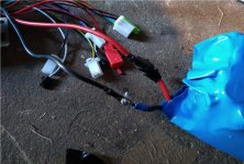
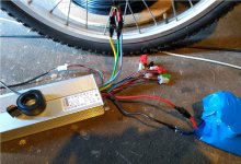
basically ive been trying to build an ebike from used laptop batterypacks. ive manager to build a few batteries but recently i havent been able to get anything to work. i dont know if im just buying from bad suppliers or maybe shorting things out before they have a chance to run. i have no idea why nothing wants to work. the only thing in this rig that isnt brand new is the motor. maybe thats blown idk
also im not using a bms at the moment till i can get at the very least a motor spinning
wierd thing i just noticed about the controller, it says it can handle 48v at 45a and its 1000w the math doesnt add up on that i dont think, maybe thats peak amps or something. idk
if i have a 48v controller, can i use a 54.6v battery?
what are the bare minimum components required for an ebike?
motor, controller, battery, accelerator, and bike?
are there any ways to test controllers?
basically ive been trying to build an ebike from used laptop batterypacks. ive manager to build a few batteries but recently i havent been able to get anything to work. i dont know if im just buying from bad suppliers or maybe shorting things out before they have a chance to run. i have no idea why nothing wants to work. the only thing in this rig that isnt brand new is the motor. maybe thats blown idk
also im not using a bms at the moment till i can get at the very least a motor spinning
wierd thing i just noticed about the controller, it says it can handle 48v at 45a and its 1000w the math doesnt add up on that i dont think, maybe thats peak amps or something. idk
Attachments
-
 IMG_20191013_144153372.jpg215.7 KB · Views: 886
 -
 IMG_20191013_144208774.jpg216.8 KB · Views: 886
 -
 IMG_20191013_144214273.jpg224.1 KB · Views: 886
 -
 IMG_20191013_144232896.jpg217.3 KB · Views: 886
 -
 IMG_20191016_193152825_BURST001.jpg194 KB · Views: 886
 -
 IMG_20191016_193227327.jpg145.1 KB · Views: 886