Throttle restrictor

bigredlions

1 µW
Joined
Mar 2, 2020
Messages
1
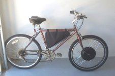
Last week I put together my first ebike kit on an old 1980's Schwinn. Everything works well.

I find with the speed restrictor on it goes too slow but with the restrictor off it goes too fast.
I'm 70 and would like to set the max speed somewhere in between and be able to slow it down for when friends use it also.

I once read it may be possible to put a potentiometer between the throttle and the controller.

I think the kit came with a fairly standard Throttle (with on/off switch)

Can someone tell me what colour wire I should put the potentiometer on and what ohm it should be.

Thanks
Screen Shot 2020-03-02 at 8.48.02 AM.png
newbike.jpg
 
Just use the restrictor when other people use it, and over time you will get use to the availability of full power when you need it by throttle, do you have closeups of the front hub install? keep it simple.
 
bigredlions said:
I once read it may be possible to put a potentiometer between the throttle and the controller.

I think the kit came with a fairly standard Throttle (with on/off switch)
Yes, this is totally possible. One challenge is to figure out which wire is the throttle signal. Usually black is ground and red is 5v. The signal line could be any color and there is no standard for this. You can find it by using a voltmeter and measuring the remaining wires to find the one that changes voltage with throttle movement. Typical throttle signal will sit a little under 1v at no throttle and go up to around 4v at full throttle.

Once you find that wire, you can either try putting a resistor or pot in series with it, or use a pot to make a voltage divider.
Some controllers will fault if they see the throttle signal voltage go too high or too low. It's a safety feature.

If you measure the resistance between the throttle wire going to the controller and ground with power off, it will tell you the input resistance of the controller. Typical is around 20K ohms. If you put an equal resistance in series with the signal line, it will limit the throttle to about 1/2. If you know the input resistance and what % of top speed you want, we can estimate the needed resistance.

Another way to do the same thing is to put a resistor in series with the 5v line going to the throttle. Resistor would be much lower value, like maybe 500 ohms in this case. When I say resistor, it could be a pot so you can adjust it.

I would try with a pot and clip leads to see what value works, then go for fixed resistors or a pot that will max out at the right value.
 
fechter said:
Another way to do the same thing is to put a resistor in series with the 5v line going to the throttle. Resistor would be much lower value, like maybe 500 ohms in this case. When I say resistor, it could be a pot so you can adjust it.

I would recommend putting the resistance in series with the 5vdc power line as opposed to the output line.
Doing so will keep from adding a dead zone between full off, and the point at which the motor starts.

Please see in this thread section, modification for hall sensors---> #2 Ending Voltage/ Maximum Speed Mod... for specifics, as well as a chart that shows the outcome of mod.

https://electricbike.com/forum/foru...on-testing-and-modification?p=70588#post70588

You can also scroll up and see tips on how to determine correct wiring and other useful information on hall sensor throttles.


Regards,
T.C.
 
I would recommend putting the resistance in series with the 5vdc power line as opposed to the output line.
Doing so will keep from adding a dead zone between full off, and the point at which the motor starts.

Please see in this thread section, modification for hall sensors---> #2 Ending Voltage/ Maximum Speed Mod... for specifics, as well as a chart that shows the outcome of mod.

Guide to Hall Sensor Throttle operation, testing, and modification. - Electricbike.com Ebike Forum

You can also scroll up and see tips on how to determine correct wiring and other useful information on hall sensor throttles.


Regards,
T.C.
I've been trying to find your pot resistor modification thread to ask you a question:
Instead of using variable resistors in the +ve and -ve lines to find the correct voltage drop, could I use a diode in each line?
They have around a 0.6V forward voltage, so would give around 0.6V to 4.4V range.
It would be cheap and simple (diode opposite way in -ve line).

thanks for all the ideas,
Paul
 
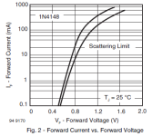
The diode forward voltage is really dependent on current. See the chart on the spec sheet for the specific diode you're using to see what it actually will be for however much current flows thru the series total of diode/resistor/diode (where resistor is the total actual pot resistance for a potentiometer throttle, or other resistance of whatever you're putting the diodes in series with).

Example; 1n4148 voltage drop goes from around 0.5v at 0.1mA to around 0.7v at 10mA to around 1v at 100mA. (-ish) (and individual diodes will vary between each other though ones in the same batch should be pretty close, if it matters to the circuit)
1705900092738.png

More info on an easy-to-follow site
 
The diode forward voltage is really dependent on current. See the chart on the spec sheet for the specific diode you're using to see what it actually will be for however much current flows thru the series total of diode/resistor/diode (where resistor is the total actual pot resistance for a potentiometer throttle, or other resistance of whatever you're putting the diodes in series with).

Example; 1n4148 voltage drop goes from around 0.5v at 0.1mA to around 0.7v at 10mA to around 1v at 100mA. (-ish) (and individual diodes will vary between each other though ones in the same batch should be pretty close, if it matters to the circuit)
View attachment 346361

More info on an easy-to-follow site
Thanks for the info. I'll do some current measuring and check what diodes cheaply available.
Should be less than 10mA so it may be worthwhile if it's not too low. There will be a 10k pot in the positive line.
I will experiment.

Paul
 
FWIW, pretty much every power supply that plugs into the walll has four diodes in it right off the plug terminals. Some of them use bridge rectifiers for that, but lots of them still use individual diodes, especialy small wallwart types.
 
I've been trying to find your pot resistor modification thread to ask you a question:

G'day Paul,
Always a pleasure to talk throttles with an interested party. This great website will set an alert if you are quoted or mentioned directly in a thread, if anyone has a question in the future...

Instead of using variable resistors in the +ve and -ve lines to find the correct voltage drop, could I use a diode in each line?
They have around a 0.6V forward voltage, so would give around 0.6V to 4.4V range.

From your description it sounds like your goal is to have your potentiometer throttle, output voltages like a hall sensored type...

Did you see the section in THE GUIDE dealing with this same issue?


*****************************************************************************************************************************************

How to make a Potentiometer "look" to a controller like a hall sensor type...

IE: Have the output voltages "mimic" the hall sensor... .8vdc to 4.3vdc, closed to WOT.

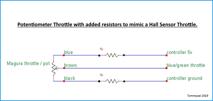
As learned in this threads previous installments... a resistor in the ground line will raise the starting voltage. And a resistor in the 5vdc power supply line will lower the WOT voltage. It's recommended to start with a 1 K resistor in each line to get started, adjust as required or desired. As the amperage used is very low (< 10mA) only low wattage resistors are required.


0w5ZRKt.jpg


2-17-2020 Feedback from successful pot throttle output modification with resistors required 1K ohms on the 5vdc, and 2K ohms on the ground... YMMV.

*****************************************************************************************************************************************

As seen in this post...

Potentiometer Type Throttles...

It would be cheap and simple (diode opposite way in -ve line).

As suggested a variable resistor mini pot probably wouldn't be required in this instance as it's been sorted out before.

So I don't see how it could be any simpler or cheaper than a couple (or perhaps 3) 1/4-watt resistors that would not vary their voltage drops and be perfectly stable. Unless you have a couple diodes of the correct current and voltage drop in your parts box already to try.

But I wouldn't want to discourage anyone from experimenting. Posted data points on your parts, current, and voltages would be appreciated if you do try the diode route.


Regards,
T.C.
 
G'day Paul,
Always a pleasure to talk throttles with an interested party. This great website will set an alert if you are quoted or mentioned directly in a thread, if anyone has a question in the future...


From your description it sounds like your goal is to have your potentiometer throttle, output voltages like a hall sensored type...

Did you see the section in THE GUIDE dealing with this same issue?


*****************************************************************************************************************************************

How to make a Potentiometer "look" to a controller like a hall sensor type...

IE: Have the output voltages "mimic" the hall sensor... .8vdc to 4.3vdc, closed to WOT.

As learned in this threads previous installments... a resistor in the ground line will raise the starting voltage. And a resistor in the 5vdc power supply line will lower the WOT voltage. It's recommended to start with a 1 K resistor in each line to get started, adjust as required or desired. As the amperage used is very low (< 10mA) only low wattage resistors are required.


0w5ZRKt.jpg


2-17-2020 Feedback from successful pot throttle output modification with resistors required 1K ohms on the 5vdc, and 2K ohms on the ground... YMMV.

*****************************************************************************************************************************************

As seen in this post...

Potentiometer Type Throttles...


As suggested a variable resistor mini pot probably wouldn't be required in this instance as it's been sorted out before.

So I don't see how it could be any simpler or cheaper than a couple (or perhaps 3) 1/4-watt resistors that would not vary their voltage drops and be perfectly stable. Unless you have a couple diodes of the correct current and voltage drop in your parts box already to try.

But I wouldn't want to discourage anyone from experimenting. Posted data points on your parts, current, and voltages would be appreciated if you do try the diode route.


Regards,
T.C.
I picked up some diodes, resistors, switches, and pots and will try different combos.
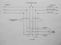
I found this diagram for a cruise control. Sorry I do not know the source, but built it. Nothing happens when switched to the pot and immediate full throttle when switched to throttle. Am trying to sort it out- maybe bad black wire Rotary Throttle.jpg connection. I used 3 single pole double throw switches as I have no idea where to get TPDT ones.
thanks
Paul
 
I picked up some diodes, resistors, switches, and pots and will try different combos.
I found this diagram for a cruise control. Sorry I do not know the source, but built it. Nothing happens when switched to the pot and immediate full throttle when switched to throttle. Am trying to sort it out- maybe bad black wire View attachment 346587 connection. I used 3 single pole double throw switches as I have no idea where to get TPDT ones.
thanks
Paul
I don't know where those resistor values came about, as after resoldering all the black wires I measure across the positive and signal wires 1.8 V to 2.6V; +ve to -ve measures 4.5V. Do you think smaller resistors?
Addendum: I forgot to say I tested it on another controller on my desk.
When I connected the pot setup to the bike controller it was again full power with no variation using the pot. Will take some more thinking and a break till tomorrow. See you.
Paul
 
Last edited:
Just to make sure we are on the same page...

What throttle make and model are you using?

What type of controller throttle control are you using? I.G. Potentiometer type (0-5vdc) or Hall sensor type (.8-3.6vdc)...?

What mode of transportation are you working on?


As far as testing goes... just a friendly reminder to keep an eye on your current usage draw on the 5vdc rail.
Jumping around between pots and resistors during testing with voltage divider circuits. (power to ground thru resistances...) It's easy to pass the boundaries of what the controller's 5vdc regulated output supply can handle. Which may be as low as 100 mA. (milliamps) To be safe I'd keep it below 20mA.
I like that you're using an old controller for the power source and testing. But an even better/safer idea would be to use a separate power supply such as a USB wall wort. or even battery power (I.G. 3- 1.5vdc batteries in series...) to test with... You can still use the controller hooked up to the throttle output with this testing set-up. But you must connect the grounds (5vdc negative) together.

From your cruise diagram, it appears that you're just switching from one variable pot (throttle) to another that's set to a certain voltage output.

I would concentrate on first getting your throttle to work properly. And then add to that to achieve your cruise voltage. Perhaps using a single switch to bypass a resistor (one of a couple in series) in the ground leg, I think the same results could be had.

That said caution is required when using such a control. This switch could be inadvertently activated by accident, even with the bike unmanned. The braking system would not automatically turn cruise off. It would have to be manually turned off, without any
automatic releases...

For these reasons I would encourage you to look into a controller that has cruise built in.
Just as an example... my Magic Pie internal controller has cruise that I use constantly and really enjoy.
It has a push button setpoint. Disengages with brakes applied. Disengages when the throttle is moved, or if the button is pushed again.
I've also seen controllers that will engage cruise after the throttle being held in the same position for a set amount of time.

I measure across the positive and signal wires 1.8 V to 2.6V; +ve to -ve measures 4.5V. Do you think smaller resistors?

Please answer the questions above... but yes it would seem that you need smaller resistors. The snippet from "the guide" below may shed some light.

As always you can use a variable pots to "dial in" the resistances needed and then replace them with a set value resistor after measuring what it's set too. Much easier than shuffling resistors in and out.

A posted picture of a hand drawn schematic of your wiring with test points and voltages would be extremely helpful. :)


*****************************************************************************************************************************
Controller...


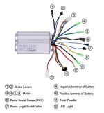
Provides the regulated 5 vdc input voltage for sensor operation. And receives the variable output voltage from the sensor to determine power output to the motor accordingly. The controller will also lock out motor operation if throttle sensor input is higher than 3.8 vdc (shorted output). Note some throttle manufactures may put a voltage drop resistor between 5 vdc+ and ground for the specific reason of making sure full voltage output stays below the controller lockout voltage. Lower than .4 vdc (open output, error code #2), or somewhere in the middle on power up (stuck throttle), which will automatically reset when the throttle is returned to the full off position. All to prevent unwanted or dangerous operation. These safeties are certainly welcome but may get in the way of throttle troubleshooting... be aware.

*****************************************************************************************************************************
 
Just to make sure we are on the same page...

What throttle make and model are you using?

What type of controller throttle control are you using? I.G. Potentiometer type (0-5vdc) or Hall sensor type (.8-3.6vdc)...?

What mode of transportation are you working on?


As far as testing goes... just a friendly reminder to keep an eye on your current usage draw on the 5vdc rail.
Jumping around between pots and resistors during testing with voltage divider circuits. (power to ground thru resistances...) It's easy to pass the boundaries of what the controller's 5vdc regulated output supply can handle. Which may be as low as 100 mA. (milliamps) To be safe I'd keep it below 20mA.
I like that you're using an old controller for the power source and testing. But an even better/safer idea would be to use a separate power supply such as a USB wall wort. or even battery power (I.G. 3- 1.5vdc batteries in series...) to test with... You can still use the controller hooked up to the throttle output with this testing set-up. But you must connect the grounds (5vdc negative) together.

From your cruise diagram, it appears that you're just switching from one variable pot (throttle) to another that's set to a certain voltage output.

I would concentrate on first getting your throttle to work properly. And then add to that to achieve your cruise voltage. Perhaps using a single switch to bypass a resistor (one of a couple in series) in the ground leg, I think the same results could be had.

That said caution is required when using such a control. This switch could be inadvertently activated by accident, even with the bike unmanned. The braking system would not automatically turn cruise off. It would have to be manually turned off, without any
automatic releases...

For these reasons I would encourage you to look into a controller that has cruise built in.
Just as an example... my Magic Pie internal controller has cruise that I use constantly and really enjoy.
It has a push button setpoint. Disengages with brakes applied. Disengages when the throttle is moved, or if the button is pushed again.
I've also seen controllers that will engage cruise after the throttle being held in the same position for a set amount of time.


Please answer the questions above... but yes it would seem that you need smaller resistors. The snippet from "the guide" below may shed some light.

As always you can use a variable pots to "dial in" the resistances needed and then replace them with a set value resistor after measuring what it's set too. Much easier than shuffling resistors in and out.

A posted picture of a hand drawn schematic of your wiring with test points and voltages would be extremely helpful. :)


*****************************************************************************************************************************

Controller...


Provides the regulated 5 vdc input voltage for sensor operation. And receives the variable output voltage from the sensor to determine power output to the motor accordingly. The controller will also lock out motor operation if throttle sensor input is higher than 3.8 vdc (shorted output). Note some throttle manufactures may put a voltage drop resistor between 5 vdc+ and ground for the specific reason of making sure full voltage output stays below the controller lockout voltage. Lower than .4 vdc (open output, error code #2), or somewhere in the middle on power up (stuck throttle), which will automatically reset when the throttle is returned to the full off position. All to prevent unwanted or dangerous operation. These safeties are certainly welcome but may get in the way of throttle troubleshooting... be aware.

*****************************************************************************************************************************
I would love to buy better controllers with cruise control but I have 2 8T macs from eunorau on 2 bikes that have no label controllers. I cannot find any guide to suitable controllers that will handle the high electronic rpm except for baserunners which are pretty expensive here.
The cruise was just a luxury as I want to do long trips and have bought a second 20Ah battery for the rack.
I am mainly interested in giving a softer start to the throttle ( ordinary half twist hall ). I will do the resistor in the negative line mod. How does a voltage drop resistor raise the start voltage? Is the throttle a load? I'm trying to get my head around it.
thanks for your help
Paul
PS I will keep on experimenting.
A follow on: Put 1k resistor in black throttle wire- motor completely dead; took back out, everything normal. I think for the time being I'll quit while I'm ahead and go for a ride.
Thanks again
Paul
 
Last edited:
Back
Top