Kelly KLS-S Controller Setup, will this work?

Bas

10 W
Joined
Jun 20, 2019
Messages
84
Hi People,

I really need some help, hopefully I can find it in this Forum.

I bought a chinese scooter with 2 wheel engines and 2 controllers, 2x2800w power. The scooter is 60v, with a 46Ah Panasonic PowerPack.
Very fast already, but because a controller broke, I thought this is the moment to make it faster.

The stock controllers only do 40A each, and 80A for 20 seconds. The wheels are 2800w each, so 40A is not very much was my conclusion after reading a lot about it.

So I bought a Kelly KLS 7218S as a replacement.

For the second controller I also bought a different stronger controller, which arrived before the Kelly arrived, so I installed that one already. Proud of myselve, 3 months ago I didn't even know what a controller was, now I already replaced one and got it to work, without burning the house down.

I decided to replace them both because I was pretty sure the stock controller and display would not accept a foreign controller, I read somewhere. Which was a good guess, I found out later..

So the first new controller was installed, the engine seems very happy with it on the blocks, I decided not to take it outside yet and wait for the Kelly to arrive, so I could judge the 2 new controllers together, really really looking forward to that moment..

I dreamed about it every day till yesterday the doorbell rang and the mailman handed me over the box from Kelly..

After opening it up, some disappointment, no instructions in the box. Which made me a bit angry. It took me a couple of weeks to choose the Kelly, so I asked for info with the Kelly salespeople, but they were very unfriendly, like they didn't want to sell controllers. Reading my questions, but answering often 2 days later. Very hard to speak with anybody, they just didn't answer my chats.

Very very customer unfriendly, I choose the controller myselve.
So no instructions. I found them on the Kelly website, opened the box further and a kinds of strange opject came out of the box. Later I understood it was a diodr and a capacitor, never heard of this. The I read in the Kelly website that my brand new, very expensive Kelly controllee would blow if I wouldn't use those articles.

Further more I have big difficulties understanding their instructions. Very clear not for noobs instructions, not in my own language(I'm Dutch) and with 1 little mistake a dead controller.

Still I am not yet sure enough to conmect the wiring to the battery pack, because now I am in doubt if I wired ot right.
Because I think I see in the wiring diagram an outer ring of wiring to protect and for the key switch?

I expected the controller to have that cable already!
Same with a power + and - wire, we have to make them ourselves?
Why THEY don't do it for their customers. The other controller I bought already had all this and more!

And where to I find the cable for the head and taillights?
That is the power + cable, made by ourselves?

So I have everything wired, but to scared to try it, although it could be right. If 1 misstake is fatal, I decided to be patient and wait for somebody to judge it first.

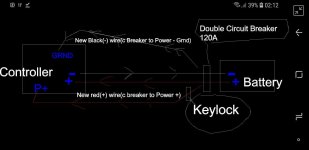
I have added to this post my Setup.
Could somebody tell me:
With this setup, when I connect it to the battery, will I be riding proudly, or will the sparks be flying around? :? :oops:

Thank you very much in advance, greetings Bas :)

My bike on youtube. It is really fast, about 85km/h
People think an UFO is passing by because of lasers and lightning :lol:
Link: [youtube]https://youtu.be/YZ0V1c6lE9c[/youtube]
 

Attachments

  • KellySetup.jpg
    KellySetup.jpg
    37.2 KB · Views: 4,822
Hi there.

I wouldn't say that the Controller explodes if you don't precharge but it can take damage especially if you have a very low resistance Battery pack.

The diode is only there for the relay, you can just use the green resistor to precharge the Capacitors inside the Controller, this should be done with just about any Controller out there.

In order to power it up you have to connect pin7(pink wire) to B+ after you precharged the Caps.
At this point you can initiate the Hall angle identify procedure (type 170 in the auto indent box and cycle the ignition or pin7) either via Bluetooth or the PC dongle.
 
Hi!

Thank you so much for the reply! :) I feel a bit embarrased to come with this noob questions...

*1: So the little wiring diagram I made is ok?(except for the green resistor which I will use).

*2: I can add this 2 wires(1 wire to the pink power +(pin 7) and 1 wire to the (pin 6) ground wire) straight to circuit breaker? The circuit breaker seems an easy and safe spot to mount the new power + wire(to pin7) to the battery(+) wire, together they go to controller.
Easy, so I don't have to solder wires then, although I can solder if necessary
Same with the new ground wire to pin 6, make it join together at the circuit breaker with the battery(-)wire to controller.

*3: The keylock, can I use a keylock built in a throttle?

*4:Now.. the green resistor.. How do I charge that thing? Hold it against the B+ wire from controller for 20 seconds and then connect the wire to the battery?

I Still have to be patient for another week, before the circuit breaker will arrive. I have to be patient for another week..

Because the original setup of the scooter doesn't seem to have resistors, neither circuit breakers, fuses or any kind of security.
I read somewhere on the internet though, it's circuit breaker/fuse will probably be the display.. and the alarm system, which is part of the lock system which also supplies 60v to the head lights

But I have 2 controllers. For now I setup the Kelly separate. Make it work with a simple throttle, standalone, not yet connected to controller B. When it works separate, I will couple the Kelly to the other, allready working new controller to join together.
But now first the Kelly.. :) :)

Again, thank you so much for any advice, I can use every advice!!!

Greetings Bas

EDIT:pS: Or is there a way I can already try without me having to wait for another week for the Circuit Breaker to arrive?...Using an empty bottle as circuit breaker or so... Really want to try, have been waiting so long...., but don't want to destroy because I'm impatient.. Those are mistakes of the past.. :eek: :eek: :oops: :oops: :x :lol:
 
Bas said:
Hi!

Thank you so much for the reply! :) I feel a bit embarrased to come with this noob questions...

*1: So the little wiring diagram I made is ok?(except for the green resistor which I will use).
Looks a bit crazy but I guess yes

*2: I can add this 2 wires(1 wire to the pink power +(pin 7) and 1 wire to the (pin 6) ground wire) straight to circuit breaker? The circuit breaker seems an easy and safe spot to mount the new power + wire(to pin7) to the battery(+) wire, together they go to controller.
Easy, so I don't have to solder wires then, although I can solder if necessary
Same with the new ground wire to pin 6, make it join together at the circuit breaker with the battery(-)wire to controller.
You need a wire that goes from B+ (or circuit-braker) to pin7, this will turn on the ignition no need for a ground wire

*3: The keylock, can I use a keylock built in a throttle?
Yes, just take the B+ wire to one pin of the switch and the other wire goes to pin7

*4:Now.. the green resistor.. How do I charge that thing? Hold it against the B+ wire from controller for 20 seconds and then connect the wire to the battery?
Yes, you can check the progress with a Voltmeter by measuring the potential between B+ and positive terminal of the Controller

EDIT:pS: Or is there a way I can already try without me having to wait for another week for the Circuit Breaker to arrive?...Using an empty bottle as circuit breaker or so... Really want to try, have been waiting so long...., but don't want to destroy because I'm impatient.. Those are mistakes of the past.. :eek: :eek: :oops: :oops: :x :lol:
Of course, I only rely on my BMS on my smaller EVs like e-bikes and such, I use circuit-breakers or fuses on larger Bikes/Motorcycles
 
Hi..

I tried, and it didn't work... I tried without a keyswitch, just 1 extra wire from B+ to the back of pin7.

The bluetooth dongle starts to blink fast red colour, same with the little lamps on the Kelly controller. It seems in some kind of code, but all red and my phone doesn't see the bluetooth dongle...

Greetings Bas
 
I've never seen the Bluetooth dongle blink red.
Anyways, if you look at the bottom few pages of the instruction manual you can see what the blink codes mean.
It will blink for instance if you don't have a throttle connected or if the Voltage is too high or low.
 
Display of throttle works, but blinking red lights om both controller and bluetooth dongle.
Never mind, I give up with this crap controller, spend all night, 0 result.

Trying to get support from them, but all of a sudden they don't speak english anymore, only chinese?
I Paid 200euro for a brick.
Problably they a laughing right now, selling brick to a foreigner, but I will make sure nobody I know, will ever buy one..
 
I owned at least 10 Kelly Controllers over the past 5 years without any issues.
If I can identify the error code I might be able to help you further.

If you can't identify the error code then please send me a video showing the blinking for at lest 15 seconds.
Also, make some HD pictures of the wiring.
 
Thank you.

I measure 4.9v on the purple 5V pin4.
I measure 66v on pin7 pink PWR cable.
I measure 0.6v on the green throttle signal pin..3.

When I measure the 3 hallwires from controller pin16 +pin17+pin18, pin16 has 0.0v, green pin17 has 5.66v, and pin18 has 0.0v.
When I measure the thick motor hallwires green, blue and green, 0.0v on all of them.

The bluehooth dongle fast, constant red flash.
Kelly controller it seems 4 flashes, short break 3 flashes, longer break 4 flashes, short break 3 flashes, etc.

Throttle display is working, it says I am in P, standing still, driving 0.0km/h

I will make a video right now...

PS: I have a very bad drawing, ut in the drawing I see a connection being made between pin1 motor temp and pin 6 ground. looks like a transistor? I have to do that to make it work??

Psps: I added the blue throttle wire to the hallwires voor speed info. But also tried without it, same result.

I added 2 new wires, 1 new wire from b+ and 1wire from b- black. Added them to pin7 and the black to pin6
 
No, you don't need pin1 connected if your motor does not have a temp sensor. And even if it did, if it's not the compatible type you're gonna have a hard time figuring out the correct values.

The error code seems to mean that the motor has not been through the hall angle identify procedure which is normal.
About the Bluetooth dongle, can you see it in your phones Bluetooth settings? It should be a 8 digit number and the pairing password is 1234, not to mention that it has to be an Android phone.

If pairing fails you will need a PC or laptop with a RS232 port or USB to RS232 dongle.

The voltages also seem fine but just to make sure you did buy at least the 60V Controller? The maximum input voltage for the 48V version is 60 Volts.
 
Hi,

I have the Kelly KLS7218S..
Here you can see the blinks of the led..

https://youtu.be/BMk55w-dkAA

With this errors, could the reason be the new wire to B+ I made, came loose?
 
The ignition key, it doesn't matter if switched of not, the display is allways on. Switched on and off. So there is something no right there, but I don't think it causes this problems now
 
I am just going to try hall wire combinations, see if I can find a combi that makes the wheel move.. I can sit here and stare at the damn thing all night, but that's not going to make it move.. ;)
 
You probably won't be able to make it spin like that at least not efficiently.
I suggest you unplug everything and just connect the B+ and B- and the ignition and see if you can at least pair to program it.
 
eee291 said:
You probably won't be able to make it spin like that at least not efficiently.
I suggest you unplug everything and just connect the B+ and B- and the ignition and see if you can at least pair to program it.

I just uncoupled the 5 thin hall wires from controller. Same result, very fast red blinking bluetooh dongle. Display from throttle still works, no difference.

I have got blue bluetooth donglw connected? I hope I don't need other parts, to connect to their programm??

Thanks for the advise, much appreciated..
I'm getting a little sad though.. Really not expected this.
 
Good, now you need to sideload and launch the AC Aduser App from here: https://kellycontroller.com/wp-content/uploads/kls/ACAduserEnglish-KLS.zip
and type 170 in the Identification Angle box where it previously said 85.

After you turn the Controller off, reconnect the Hall plug (you don't need to find the combination, it will do it automatically, so put the pins back into the plug to prevent a short circuit) and power the Controller on.
Make sure your motor/Wheel is in the air so it can do the Identification Angle procedure for the next 30 seconds after it has finished it will blink, you can cycle the ignition again and you will see a constantly lit green LED, now the Controller is ready to be used.
 
eee291 said:
Good, now you need to sideload and launch the AC Aduser App from here: https://kellycontroller.com/wp-content/uploads/kls/ACAduserEnglish-KLS.zip
and type 170 in the Identification Angle box where it previously said 85.

After you turn the Controller off, reconnect the Hall plug (you don't need to find the combination, it will do it automatically, so put the pins back into the plug to prevent a short circuit) and power the Controller on.
Make sure your motor/Wheel is in the air so it can do the Identification Angle procedure for the next 30 seconds after it has finished it will blink, you can cycle the ignition again and you will see a constantly lit green LED, now the Controller is ready to be used.

I got connected via bluetooth!! :) :)

So now I'm in the android app.. It gives a red message the hall were not connected correctly! Glad to be connected!! :) :D :)
 
There is no correct way to connect the Halls you just need +- to be correct the rest is handled by the Identification Angle procedure.
 
I keep getting the think red warning line in the android app, saying hall sensor error. Please see screenshot.

I think I know the reason.. The old connector of the hallwires is a little different.. The iron peaces in the connector they don't fit very well. So I took them uit of the connector and connectes them straight. But apparently no good contact? Please see screenshot..
 
Please see attached photo of the pins(too thick) sticking in the connector. Could this be the reason? The pins are very very hard for me to mee to remobe from the kelly connectors..
 
Please see attached photo of the pins(too thick) sticking in the connector. Could this be the reason? The pins are very very hard for me to mee to remobe from the kelly connectors..
 
That's why you should crimp the new pins that you got with your Controller on them.
Also, have you tried turning the wheel while looking at the Hall ABC fields? All of them should be alternating between 0 and 1.
It is probably showing hall error because all 3 hall signals are on 0 which should only happen on a motor with 60 degree hall spacing.
Have you tried the identify procedure yet?
 
I can see a green light on the Kelly now, a positive change!! yes yes yes :D :D
 
not yet, now searching for the Kelly topic I have seen somewhere, to put in the best settings. THEN I will try if it spins. ;) But it will spin, green light on the Kelly now. First find that page with kelly settings..
 
Back
Top