I started construction on my garage so I have been busy with that lately, however it has been very rainy this week so I got a break from the construction and that gave me some time to work on the EV CA160 project. Oh, and my wife started demolishing the downstairs bathroom and laundry room and she wants me to work on that too. Oh, and my wife is pregnant and we just found out a few weeks ago, so now she won't be helping at all. So have less than 8 months to finish this yet no time to work on it!
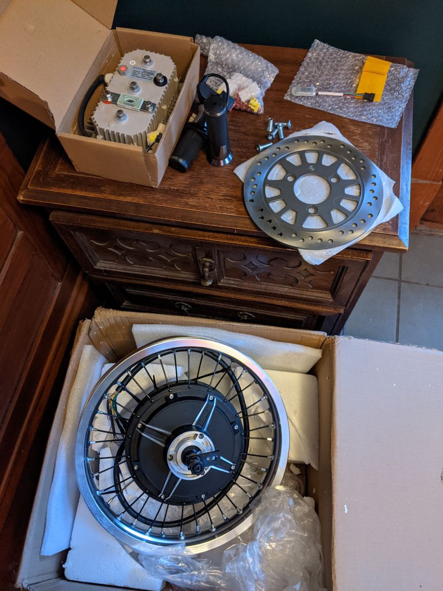
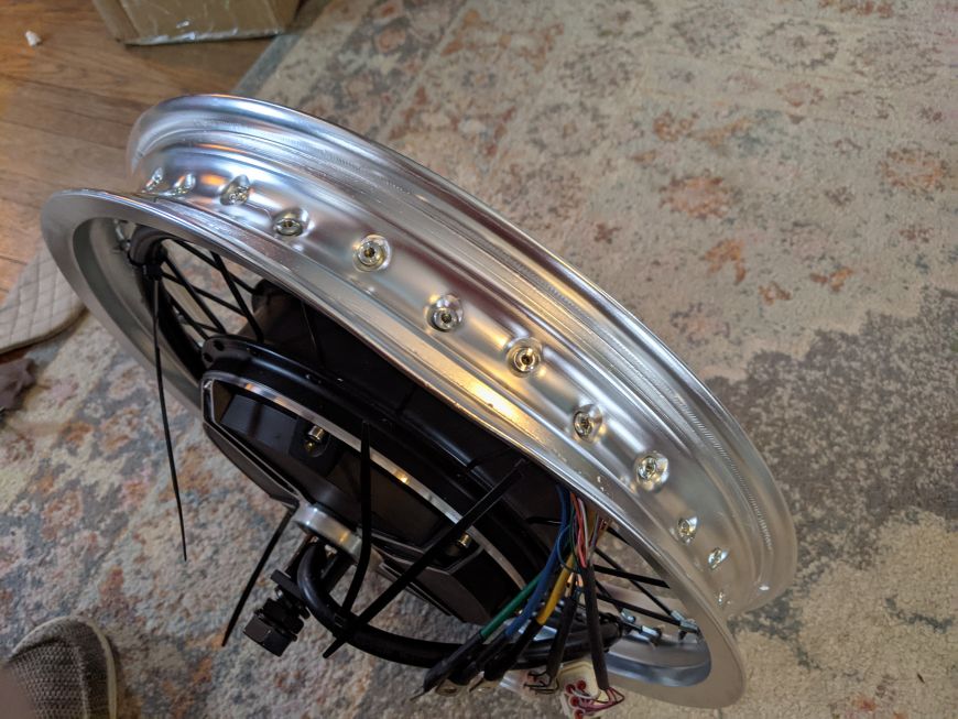
There's two problems between the swingarm and the new rear wheel that I knew I would have to deal with even before the wheel even arrived:
- the swing arm is not wide enough to fit around the hub and onto the axle. It's 190mm wide and it needs to be 210mm wide to fit the wheel.
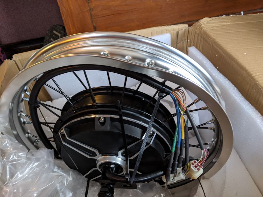
- the slots in the dropouts to hold the wheel will not work: they're too wide. The hub wheel's axle has to flat spots so that it won't spin relative to the rest of the wheel. There's a lot of torque (150 Nm max) that the hub motor puts on the axle, so this is very important. It needs to be a tight fit with no slop.
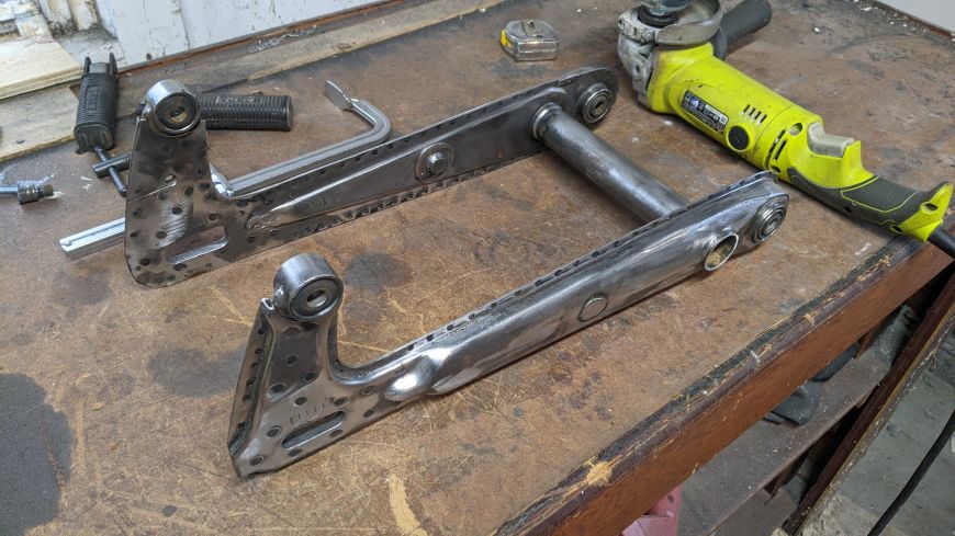
So before I could mount the motor/wheel inside the swringarm so I could securely test it, I needed to modify the swingarm. First thing I did was grind off all the old paint.
(btw, these images are all optimized for web shrunk down to an appropriate size and dimension, but if you click on them you will get the full size images)
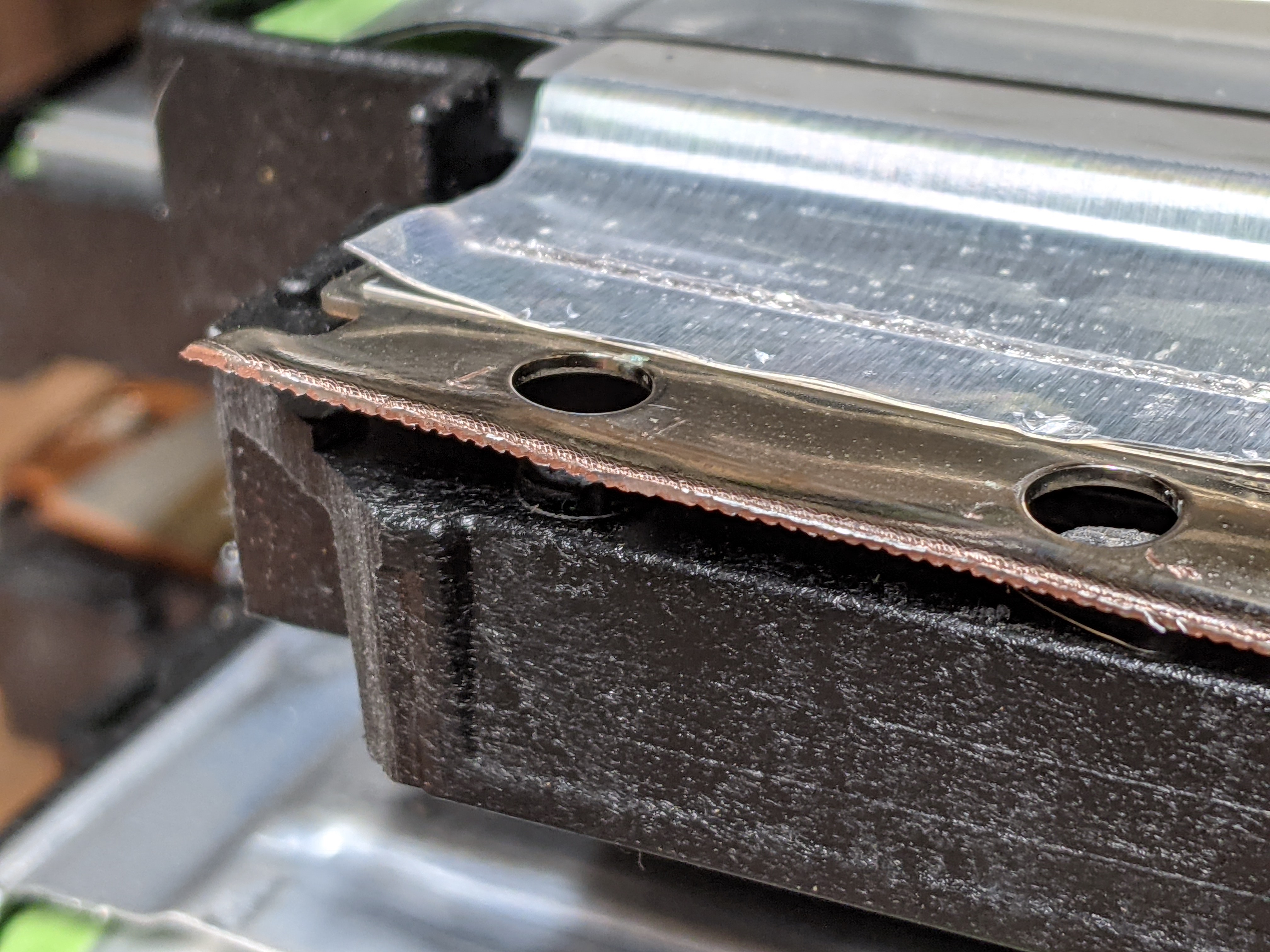
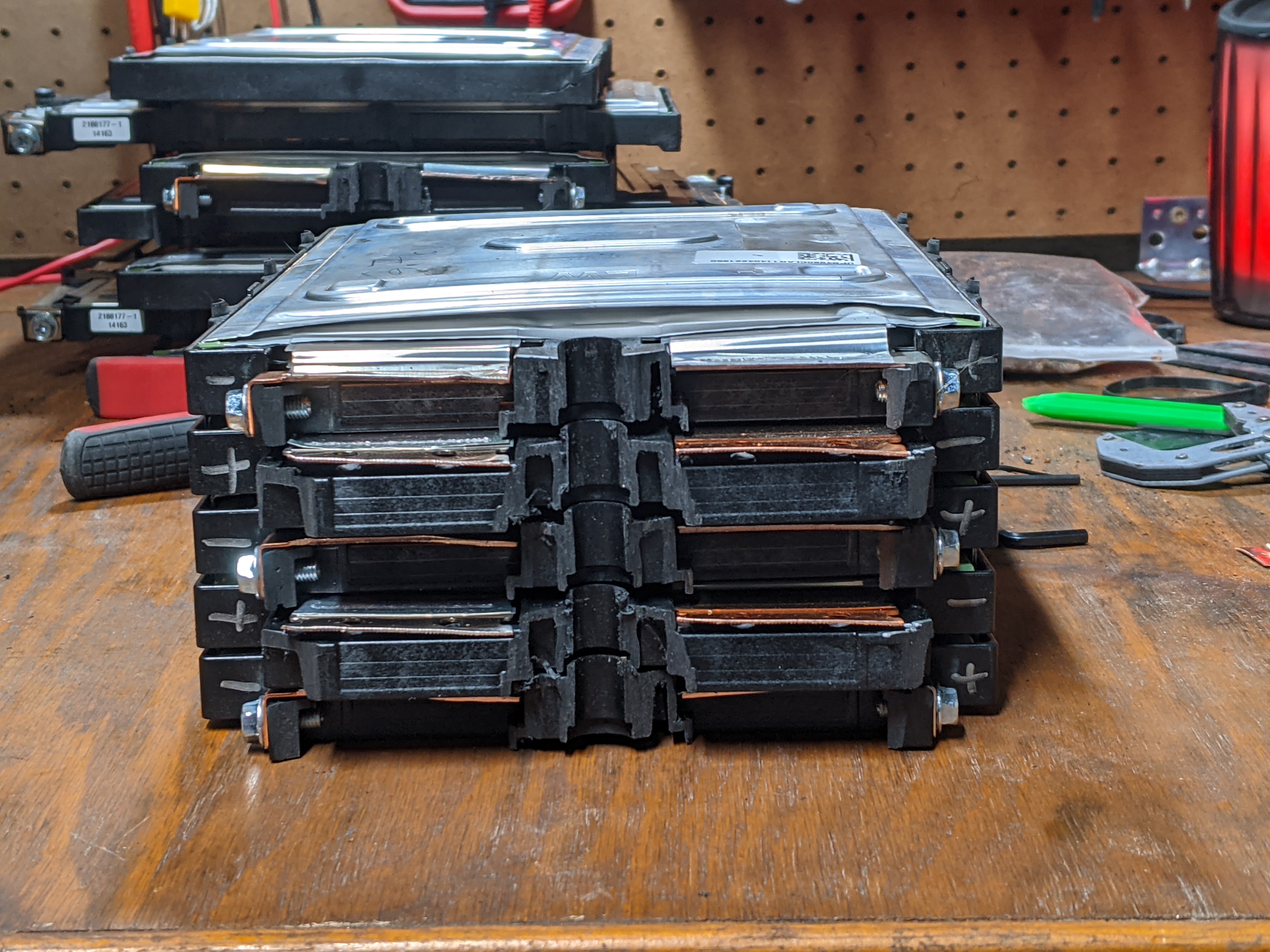
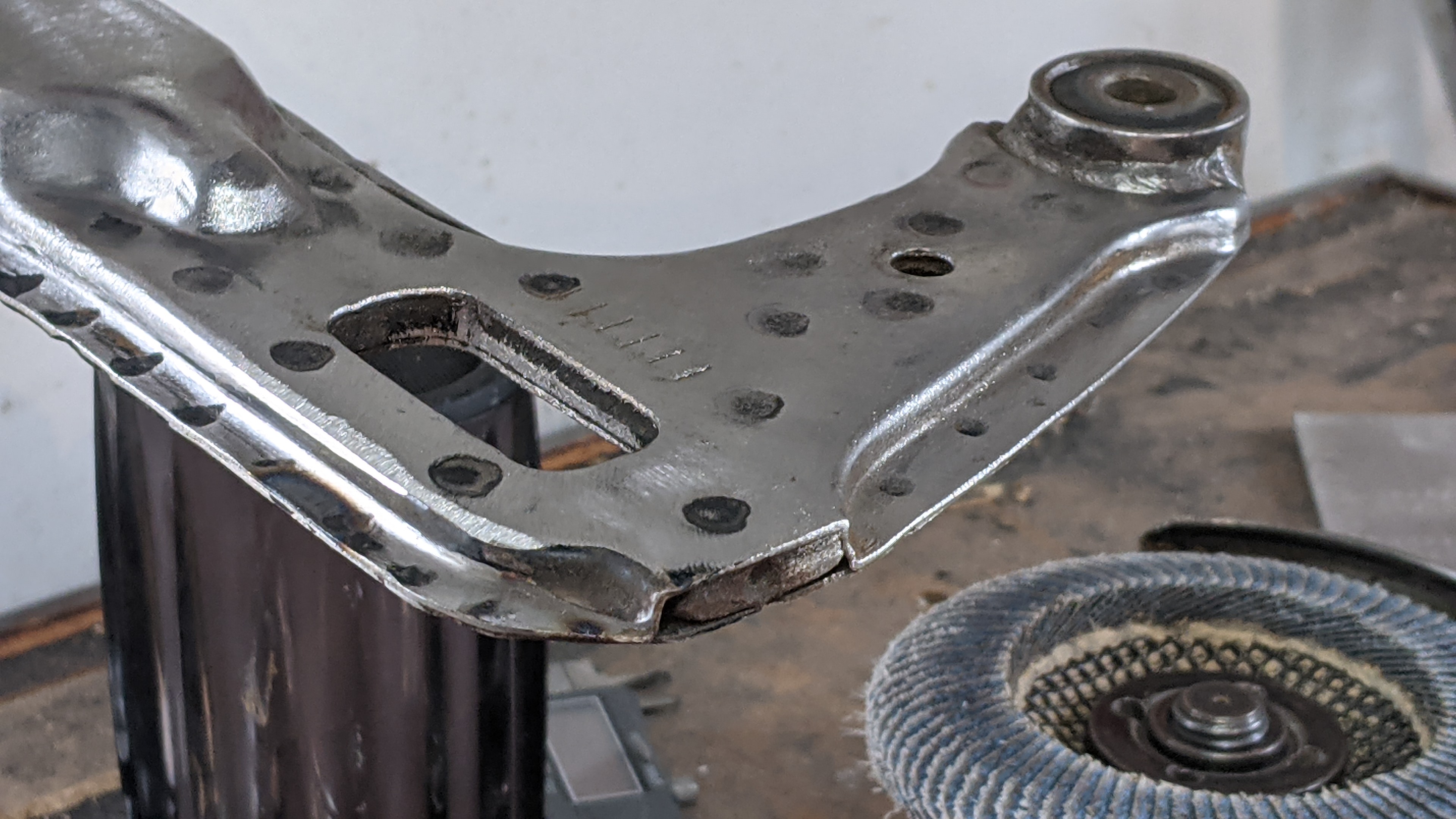
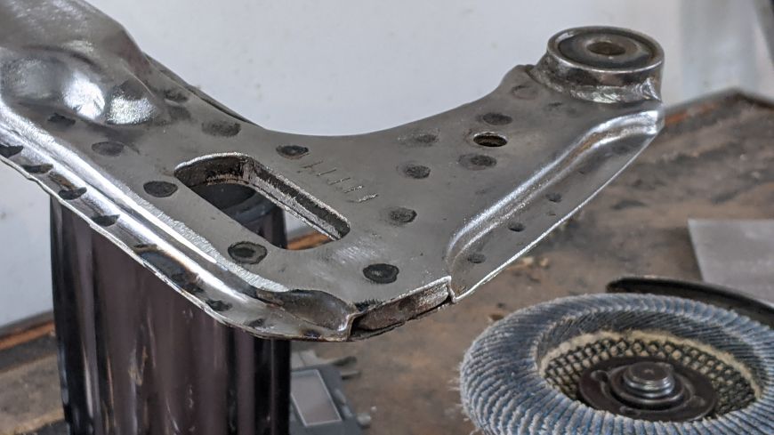
Below you can see how Honda constructed this part of the swingarm. They sandwiched 6mm steel between to sheets of stamped steel about 18 gauge. The 6mm plate in the middle was welded to the bushing for the shock, as well. Then they spot welded it all together.
At first I thought that this would be a problem for welding onto, but my friend who did the TIG welding later on assured me that it was not an issue.
Of the other EV conversions I've seen where they use a Honda Cub or similar with a hub motor like this, they first widened the whole swingarm by cutting the center tube, widening it with new material, and then welding it back up. Then they added material to the dropouts to make them the correct size for the axle.
However I thought of a better way (IMO). The outside dimension between the stock dropouts was exactly the inside dimension needed to fit over the hub. So I decided I would knock out two birds with one stone by cutting out the old dropouts and welding new ones such that the inside surface of the new dropouts would be butted up to the outside surface of the old dropouts.
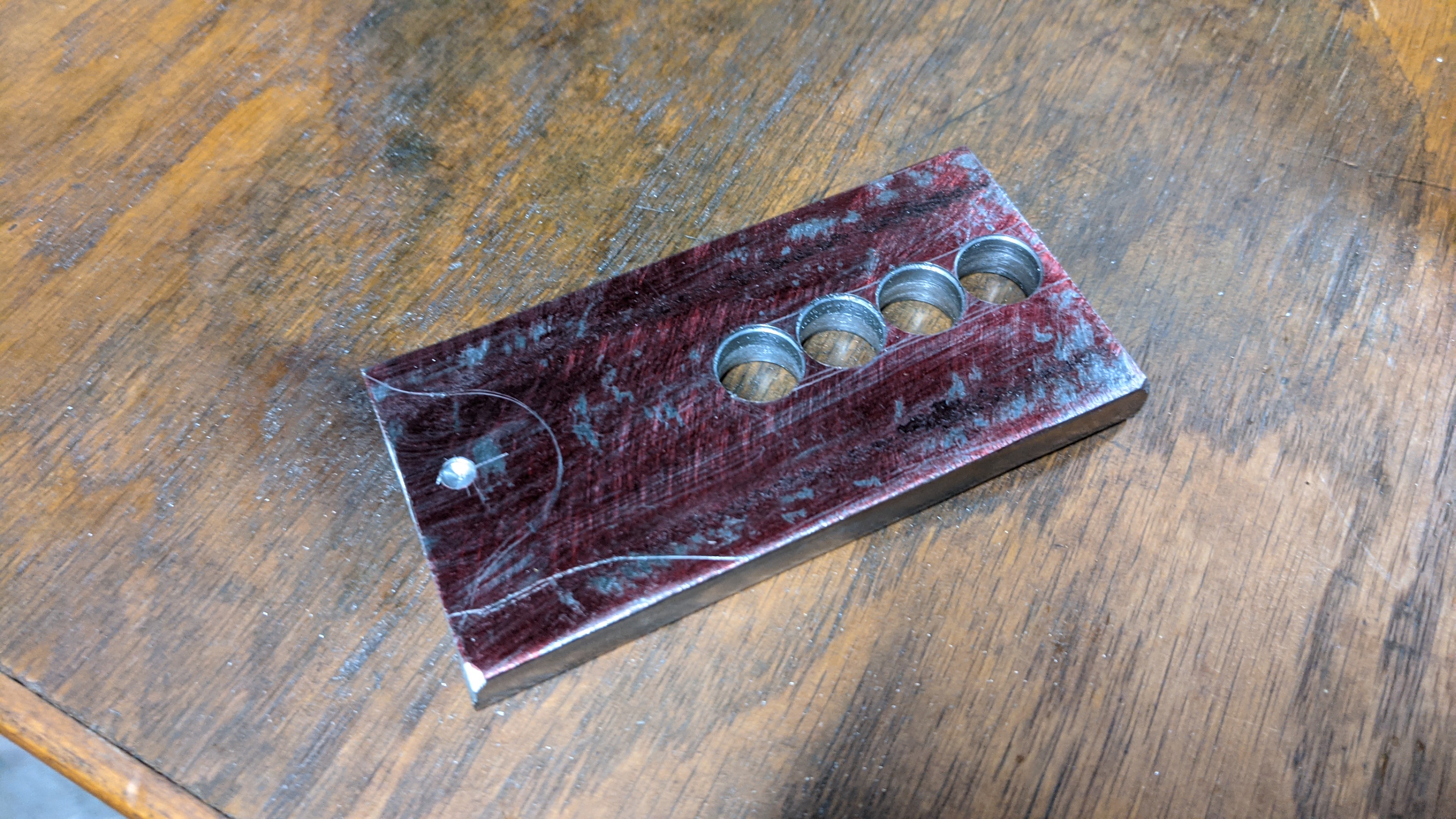
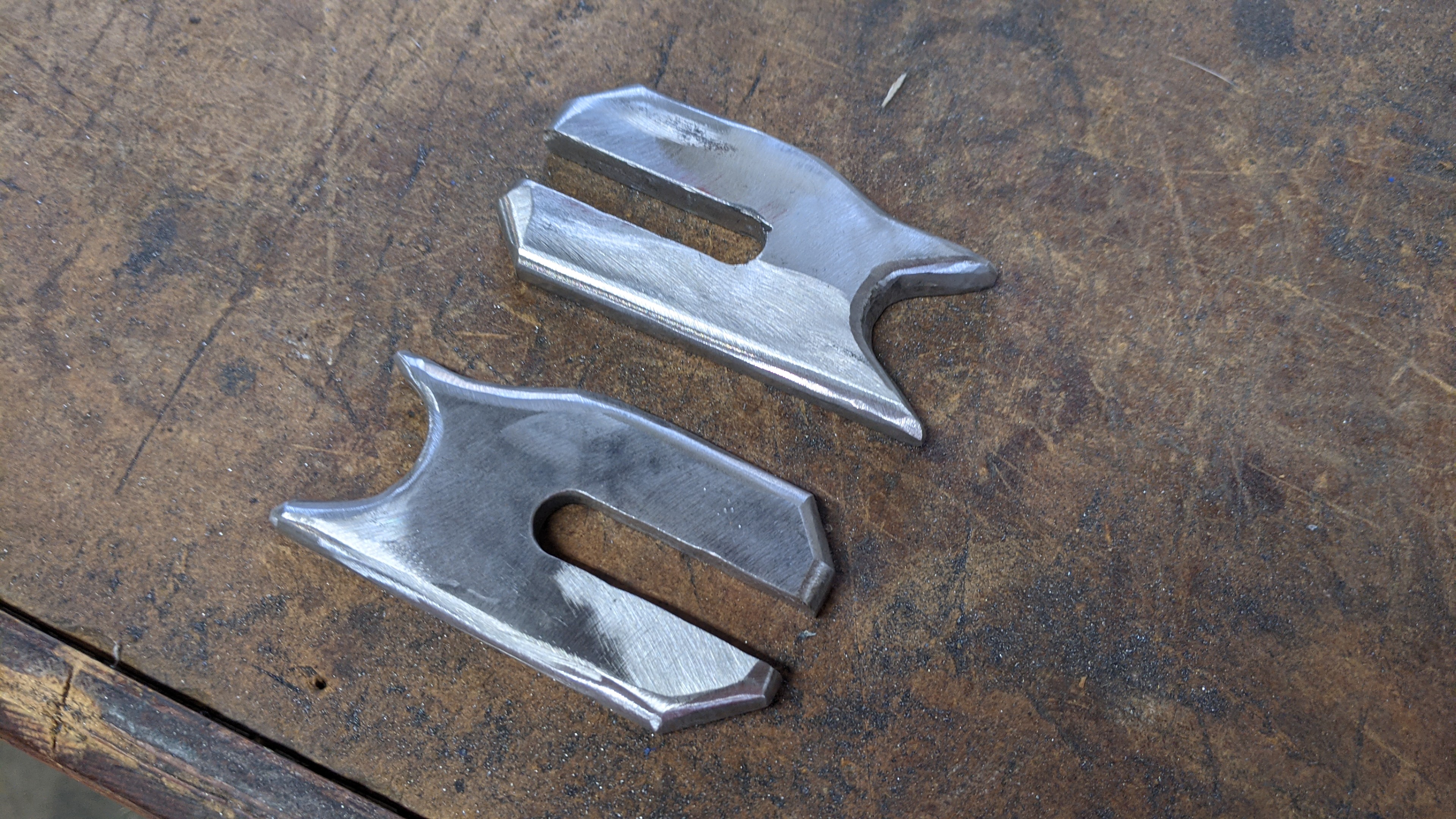
So I began "milling" the dropouts out of 3/8" steel and using a cheap HF drill press and a cutting wheel on an angle grinder. I could have designed them in a vector file and send them out to be lazer cut, but I thought it would be fun to do it myself.

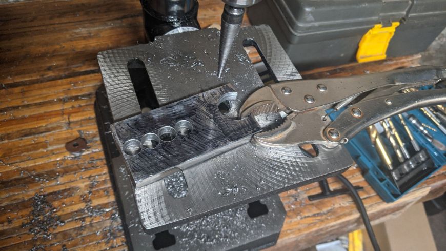
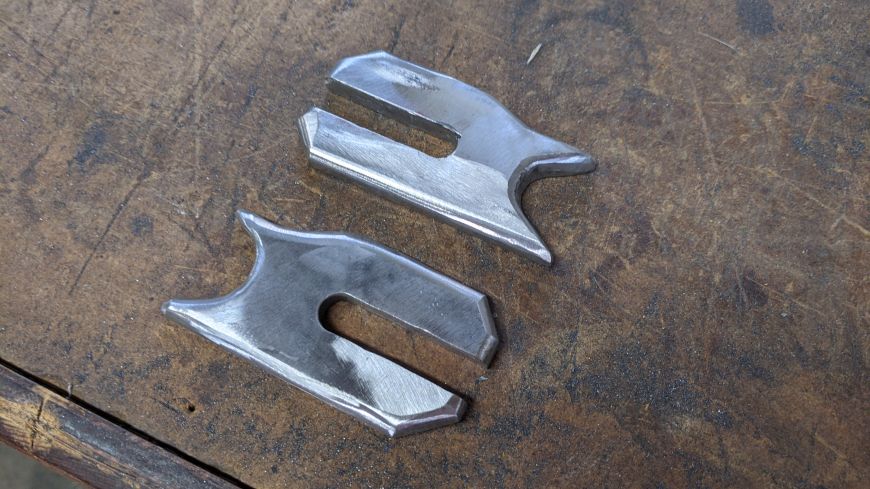
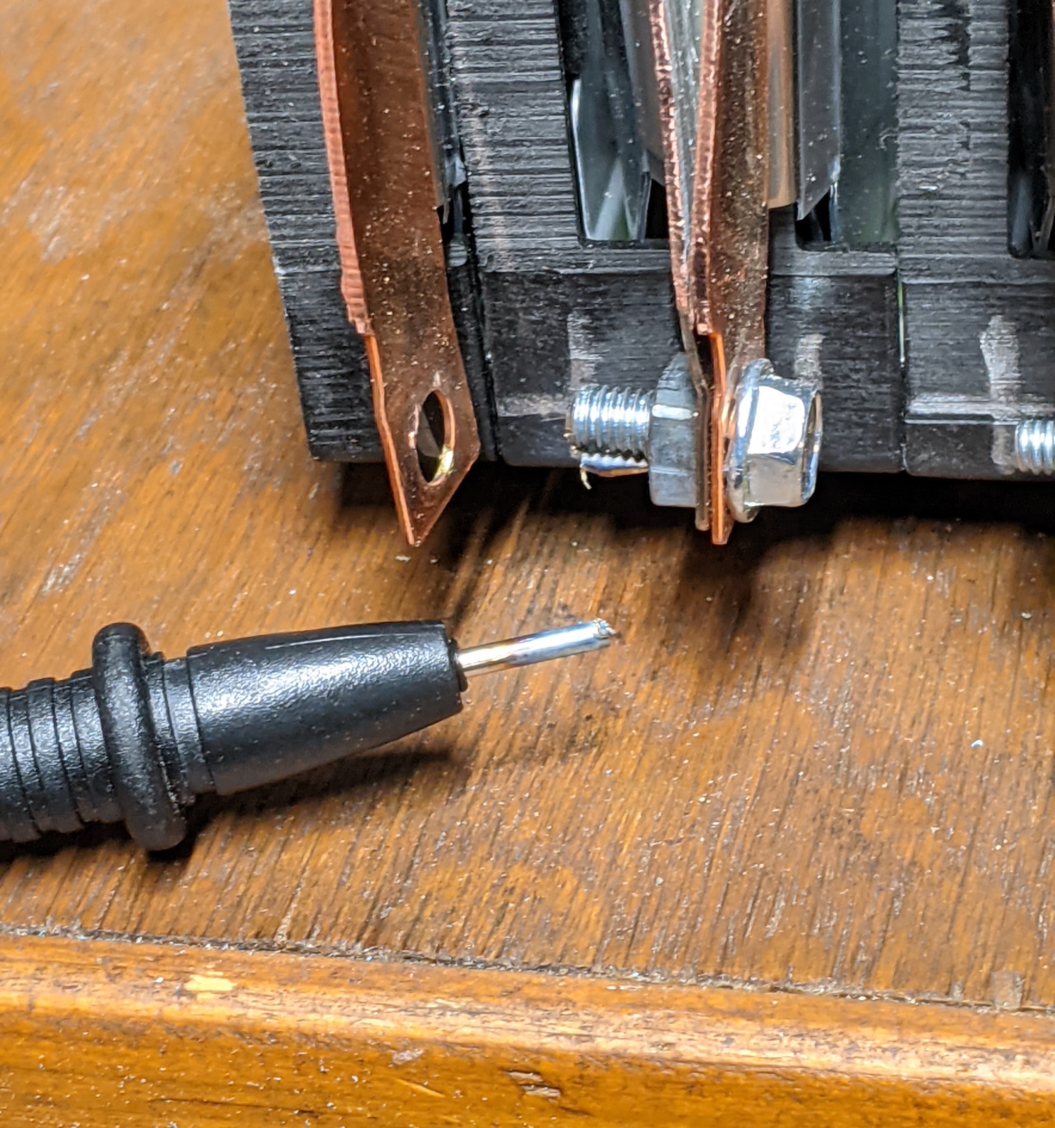
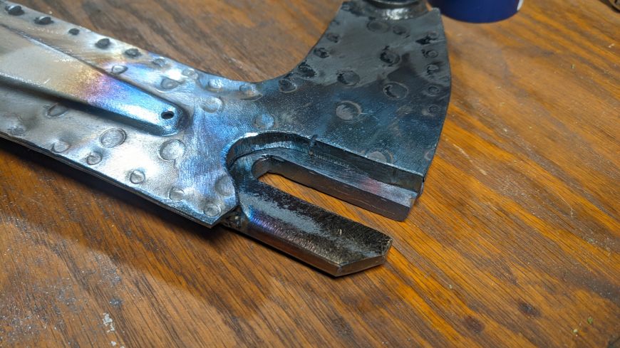
I cut the slots in the dropouts to 11.9mm (with a 15/32" drill bit) when they needed to be 12.0mm. Then I used a file to carefully and slowly enlargen them until they perfectly fit onto the axle with zero slop. I wanted a very tight tolerance so that when I hit the gas or hit the brakes hard, it wouldn't shift and slam and eventially work it's way loose. If for some reason that axle where to spin with the wheel, it would coil up the wires between the wheel and the motor controller, ripping the wires out and destroying the controller.
Then I cut away the old dropouts. I needed to remove about 30mm diameter around the axle location, so that there wouldn't be any interferance with the disc brake hardware and with the motor's wires.
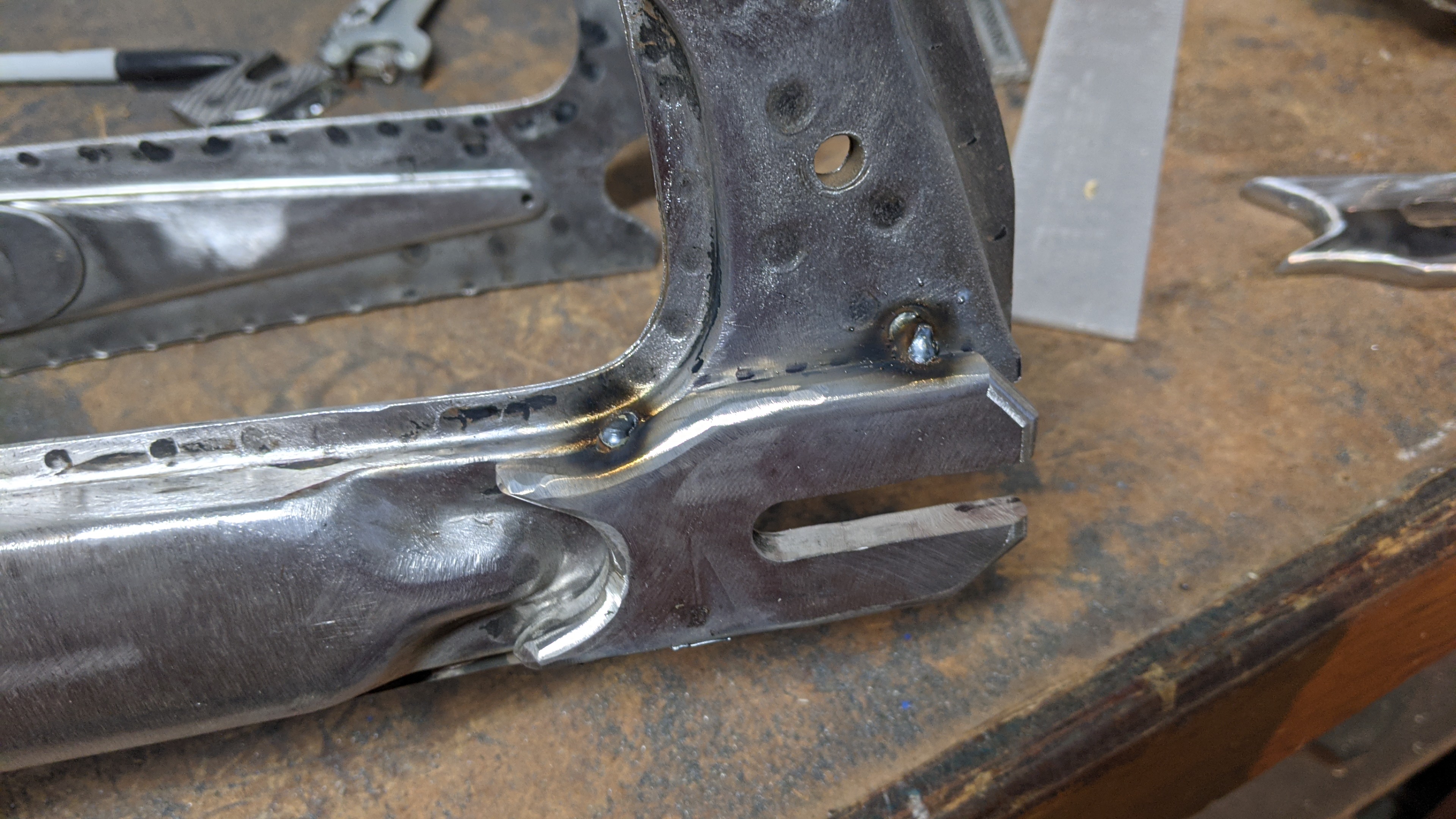
I tack welded one of the new dropouts on...

...then I used the bolts to tighten the other one on before tac welding it in place. This ensured that the two dropouts where perfectly aligned for the axle to slide in. I also made sure that the wheel was straight up and down, I did this by sight (used my eye-calipers).

Then I took it over to my friend's place and he used is 240v TIG welder.

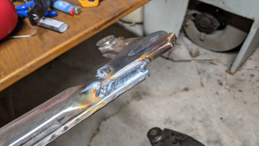
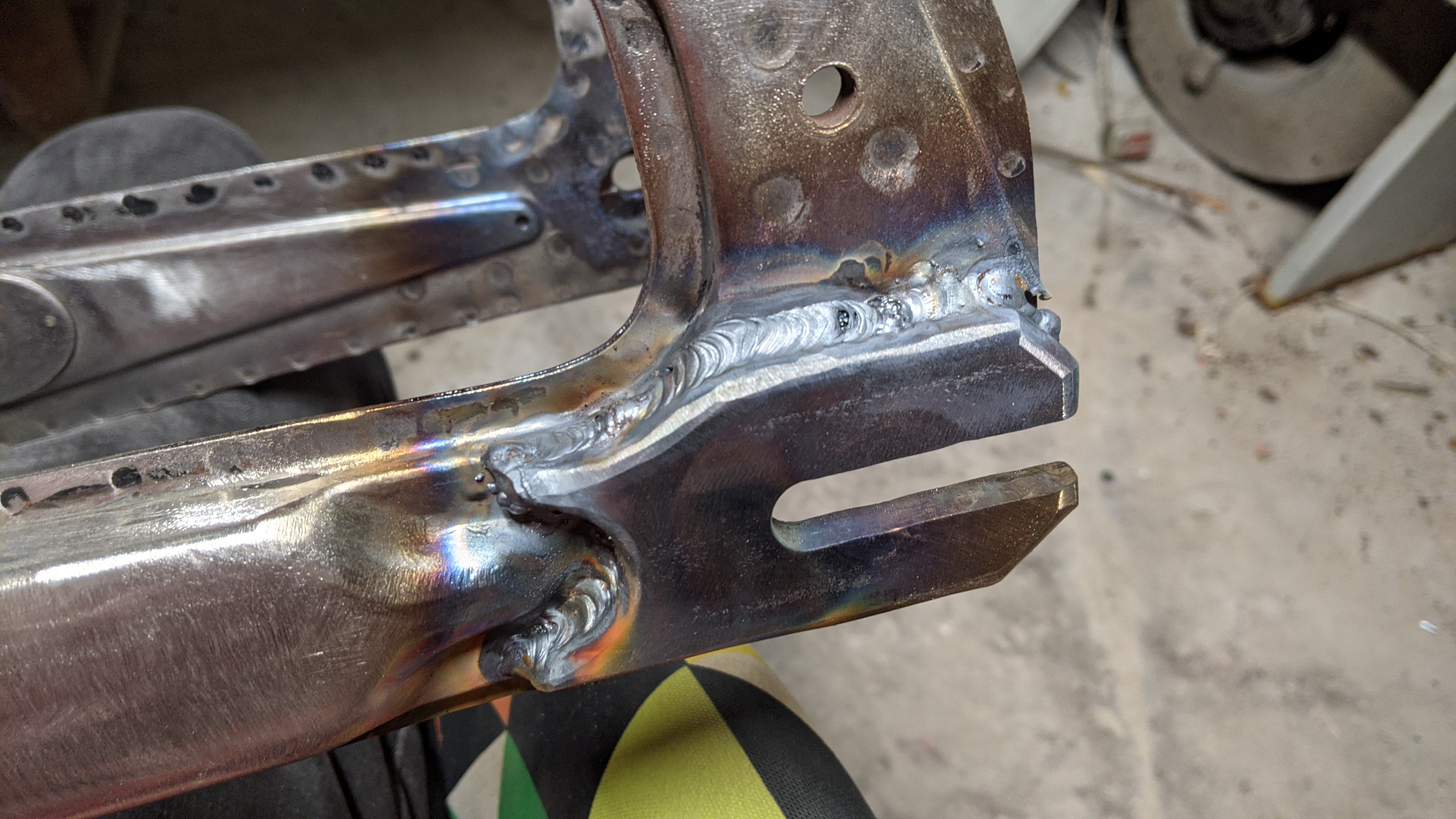
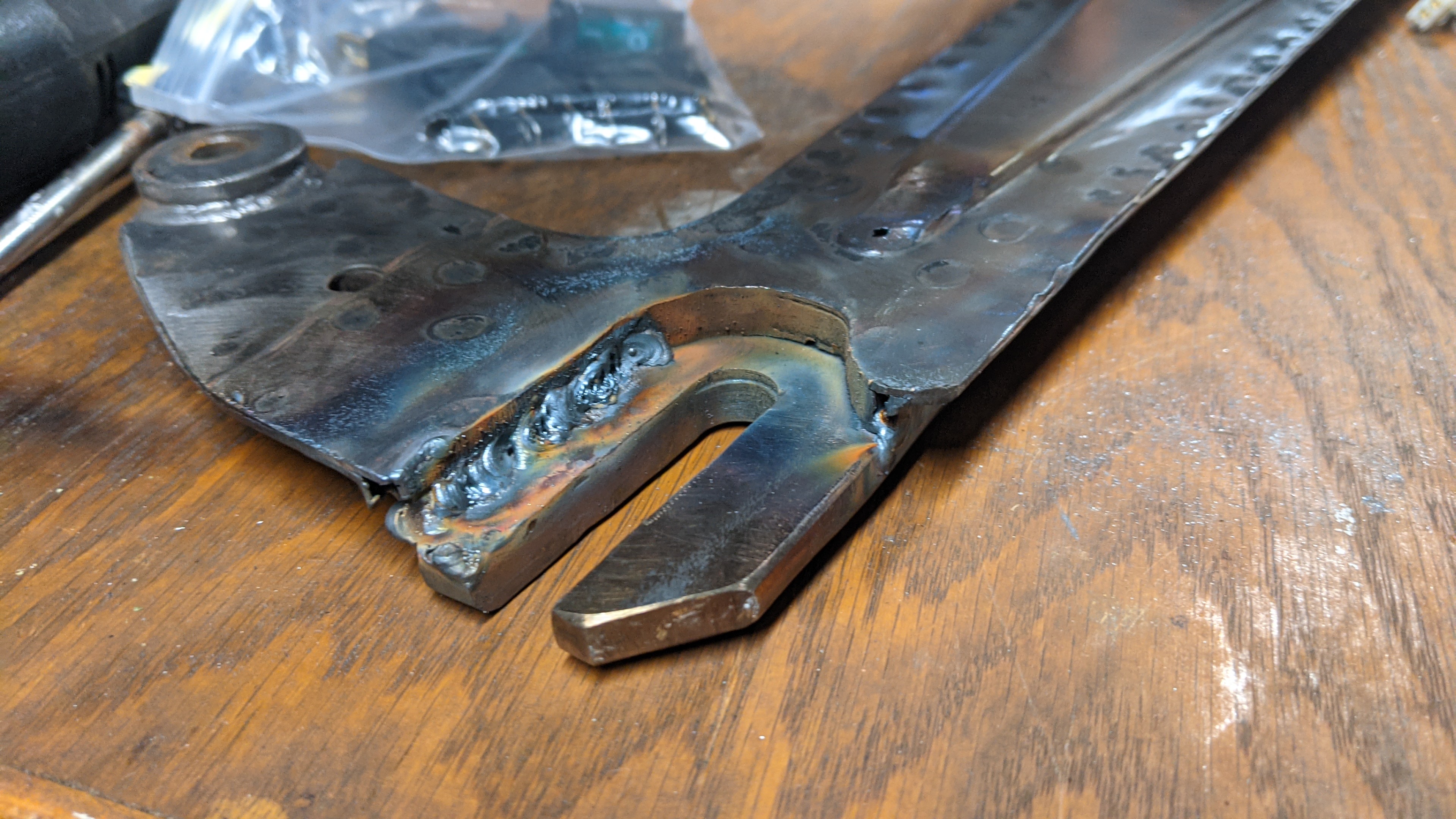
Here's why he wasn't concerned about welding it to the sandwhich of sheet metal and plate metal: because on the inside, there was easy access to weld the two plats directly to each other.
However the TIG machine was having a hard time with this spot - apparently there was a lot of contamination. My fault as I did not know that TIG welding needed the metal to be perfectly clean and free of all paint. That's also why there was a few blow outs and holes in the above photos.

So I will have to weld that area myself, and I'll use my stick welder for this because my MIG welder cannot do metal this thick. Stick welding tolerates a lot of crap in the metal.
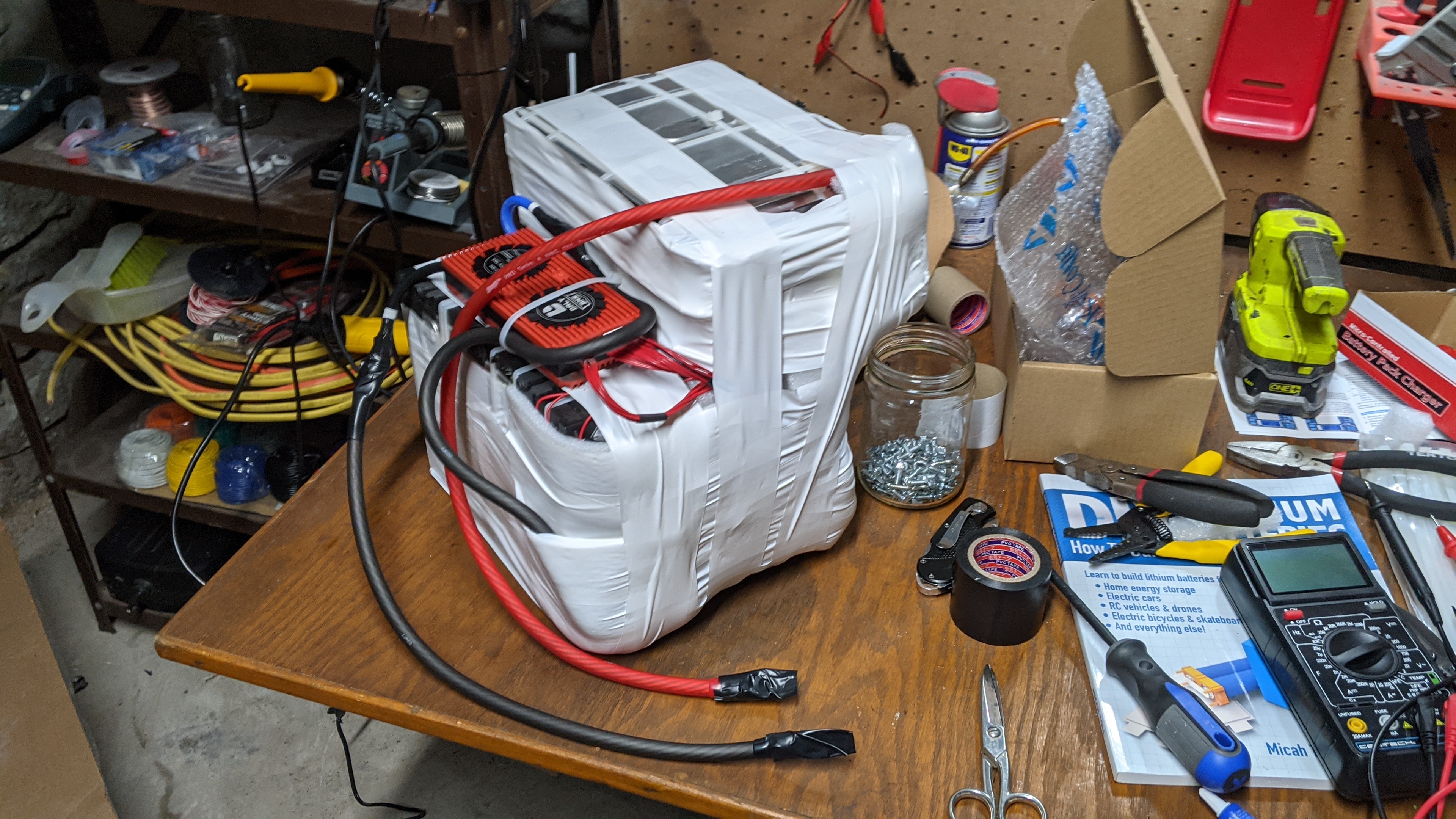
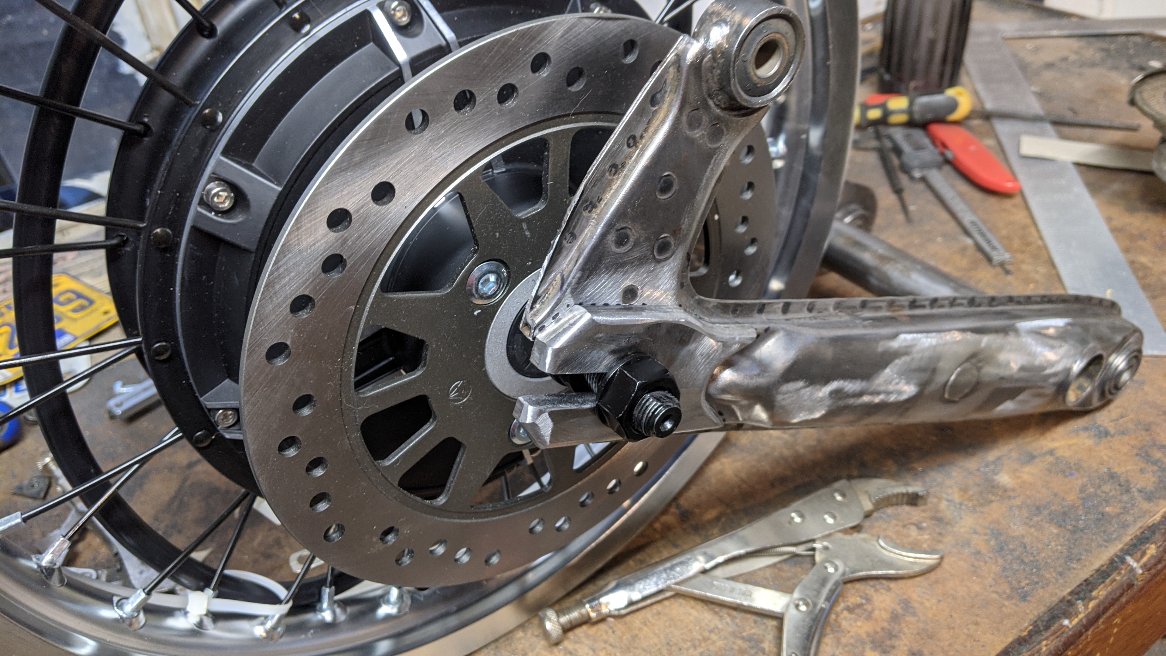
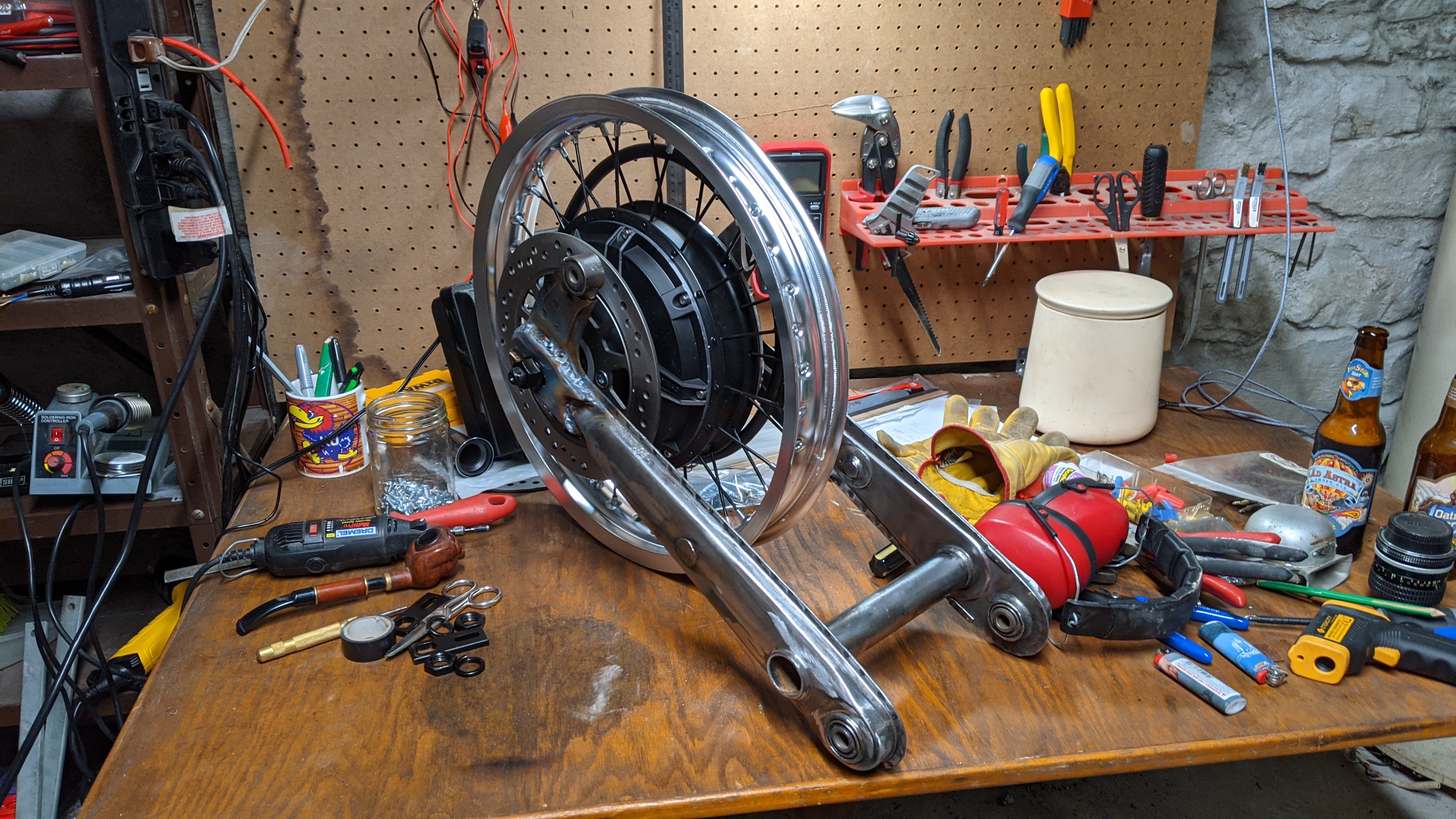
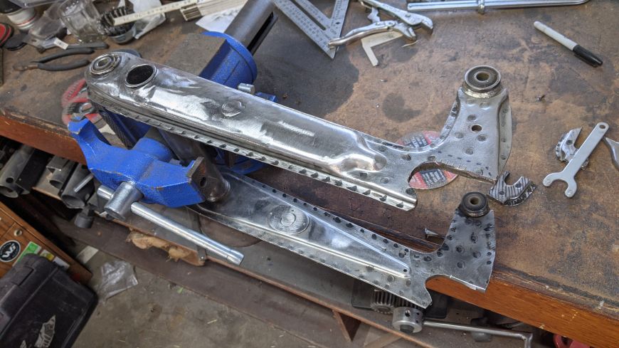
But what's important is that the wheel now fits on the swingarm!
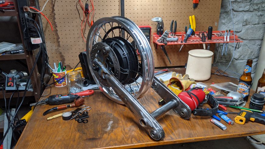
And there is absolutely ZERO slop between the dropouts and the axle! There's no need for any torque plates, and the ones that came with the wheel had a ton of slop in them.
I'm very happy with how its turning out! I have a little welding to do and a little cleaning up to do with the grinder but the hard part is already done.