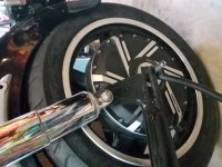
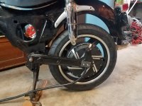
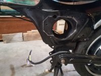
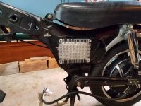
1962 Honda Benly goes electric

MACK

10 mW
Joined
Apr 29, 2020
Messages
20
Location
Tucson, Arizona
Hello all, after lurking for a time and learning a lot on the ES forum, I have of course become motivated
and I want to play too! So finally I’m ready to start my 1st EV project, and will attempt to share it (I’m a
bit of a luddite with the confuser) for your interest, and my help. Thanks

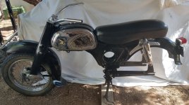
The doner bike is a ’62 Honda Benly or the “Baby Dream”. It used to be a 2 cylinder, 150cc, 16hp with a
top speed of about 75mph. It was a craigslist find… you know… it’d been sitting for a few years, covered
in the garage, so clean the tank and carb, change the oil and it should be good to ‘go'. :wink:
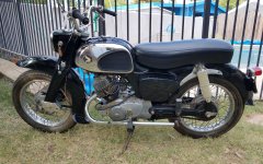
CA-95.jpg

Barely. It started but all the metal bits when I changed the oil was the sign I should have heeded and
given up. But no, I took it to a shop and spent $200 for them to pull it apart and then say, “yup, probably
not worth it. Needs a top & bottom rebuild and there’s some bent things “. Well, the engine was off,
now that’s a start.
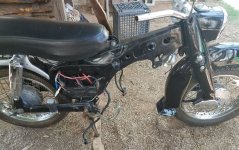
start.1.jpg

I love the classic styling and want to try to put, mostly everything back as it was (no fender chopping :D)
and plan to register it for legal road use. It’s got a VIN and was originally registered for the road so
hopefully that won’t be too big of a deal as long as I get the lights and horn working.

With the battery I’d like to do something fun, like keeping with the era and go for a 50’s space age look
and perhaps house it in a tube or, multiple cylinders where the engine was. The frame looks perfect for
dyi structural support and mounting bracket where the engine was attached.

It’s purpose (besides pure fun!) would be an in-town commuter and errand runner, so big trips would be
20ish miles. Speeds would be mostly 35-40 and 50mph max top speed would be fine, more-fast scooter
like, it’s small so that will feel plenty fast, I think I’d be scared on it at 75mph!

I realize there are a lot a variables (and different ways to do a similar thing). So I’ve made a few choices
to start me down a path and reduce some of the variables and help bring in to focus the rest of it.

First is I plan go with a rear hub motor for the added simplicity in a first build. Then in term of the
unsprung weight, this is certainly not a performance build, and the old drum brake rear wheel on it
wasn’t light by any current standard. :eek: Also re-gen braking is easy which I would like to take advantage of,
so… I’ve ordered (from qs-motors) a 16”4000W hub motor kit with KLS7245N as a controller and I told
them I planned to run it with a 72V battery.

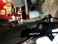
In the meantime I’m rebuilding and preparing the frame, forks, front wheel and drum brake. So far the
frame and all look as good, as the engine was bad.

So what do ya think, sound like a reasonable plan?
 
Keep in mind that Kelly controllers measure current at the phases, not the battery. So the spec from their site:
KLS7245N 30-72V 350A 100A
of 350A peak and 100A continuous is motor phase current. The actual battery current (and thus "system wattage") will be less by whatever factor that controller is setup for--if it's programmable, then you can change it within whatever range they've allowed. Not knowing that controller, I'd guess continous battery would be 50A or less; if so the system wattage would be 72v * 50A = 3600w. Controllers are not completely efficient, so you would get less than that at the motor. That might mean as little as 3000w or less, continous.

This simulation with a "cromotor" (similar to some of the QSmotors, don't know if it's similar "winding speed" to the one you're getting, so don't know if it's an accurate comparison) and 72v battery 50/100A controller, 22" wheel (should be similar outer diameter to your 16" MC wheel's tires), etc., gives about 38mph top speed.
https://www.ebikes.ca/tools/simulator.html?motor=MCRO5004&batt=B7223_AC&cont=cust_50_100_0.03_V&wheel=22i&hp=0&mass=181&axis=mph
using about 2kw motor power, about 2300w battery power (300w wasted as heat in the system between battery and road).

If your motor isn't wound for a faster speed than that Cromotor, you won't get quite as fast a top speed as you want, unless you increase the system voltage (different battery, different controller).

If your tires are larger diameter than the ~22" I used in the simulation, then you'll get a faster top speed with the equipment you have. A 24" outer diameter tire (in the same simulation) would give just under 40MPH top speed, at about 2300w motor power, and about 2700w battery power.
https://www.ebikes.ca/tools/simulator.html?motor=MCRO5004&batt=B7223_AC&cont=cust_50_100_0.03_V&wheel=24i&hp=0&mass=181&axis=mph&autothrot=false&throt=100


For range, it's probably going to take up to 100wh/mile (probably around 60-70 typical) around 40mph. To get 20mile range with worst-case mileage, you'd need 20miles * 100wh/mile = 2000wh. At 72v, that's 2000wh / 72v = ~28Ah. At typical 70wh/mile, that's 20 * 70 = 1400wh, which at 72v is ~20Ah.


Keep in mind that all of the above is assuming perfectly flat roads, no headwinds, etc. On hills, and in headwinds (and startups from a stop), the power usage will be higher. This decreases range (by increasing wh/mile). So if you expect significant headwinds, or hills, you would want to increase the battery size proportionally.

Additionally, you may wish to plan for potential detours, and/or pack aging (a battery loses capacity as it ages). Myself, I'd add at least 20-25% to any estimated battery capacity to allow for these two things.


Also speed may be slower if the controller cannot output enough power to keep the motor at full speed under that load. So if you expect this type of situation, you may need a higher-power controller. (may require experimentation with existing controller first, possibly changing settings in it's setup program to optimize for your situation).


The battery is the heart of the whole system, as it must provide all of the power, as-demanded, so it's the one place not to skimp. Make sure the cells it uses are capable of actually handling the full continuous (and peak) currents your system will demand, plus a margin to allow for pack aging, etc. If they aren't, there will be significant voltage sag, and pack internal heating from wasted power, which means less motor power (which means slower acceleration, etc), and lower speed due to less voltage under that load.

Make sure the cells are new, and well-matched, and not recycled junk or whatever-cells-were-laying-around-in-the-bins.

If you can't tell from the seller's info enough to ensure the above, don't buy from them. And remember that they'll generally tell you anything you want to hear, whether it is true or not, to make a sale. :(


Often, with a medium-large EV like this, you have enough room to use EV-grade cells. Even used Nissan Leaf cells, or new stuff like the EIG NMC C020 cells, or other similar large-format EV-grade cells, will generally perform much better, especially over time, than packs built of a bunch of small cells (like 18650/etc) (tesla's batteries notwithstanding, as they are VERY large and have special cooling, etc).

A 40Ah EIG pack like I use in my SB Cruiser trike is about 35lbs for 52v 40Ah (14s2p); 20s2p (72v 40Ah) would only weigh around 50lbs (not including containment box), and be something on the order of 8" wide by 10-11" tall, by perhaps 18" long, if configured in one row of cells. Would probably fit easily in the space the engine took up, though it would be a box shape you could make covers taht have whatever shape you want around that.
 
Thanks for the reply Amberwolf…still digesting :thumb: , initially my thoughts (for myself) are ‘pretty close’.

You were right on with my wheel at 22”, but from what I understand the controller is programmable and under features it lists “Configurable limit for motor current and battery current.” and in the spec’s it lists “Max Battery Current: Configurable.”

The motor windings I learned about after I ordered, but what I (think I) ordered are their fast windings V3
“In terms of material, V3 motor has big trunking, uses more copper, with curve magnetic steel, and has highest efficiency and speed. It is the best option for enthusiastic fans pursuing perfect and high speed.”

With the configurable current limits in mind when I looked more closely at the motor specs these two
jumped out to me • Continious current:67A • Max current:80A Peak 140A

? So I will, of course, be waiting to see what (and when) I receive, since I ordered in the middle of a pandemic and all. :roll:
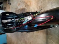
Battery advice helps, having read some of your posts on the idea of the heart of the system, it’s why I’m waiting till last for the battery, to be sure it’s the ‘right’ heart. I did have the # 72v 40Ah floating around in my head, I do want reasonable acceleration and to be ‘nice’ to the battery by not over draining it so I understand bigger can be better in this case, but I haven’t looked at the leaf or EIG cells yet, more research!

Oh, and of course all the roads are flat with no head winds! When I was bike touring down the west coast years ago our favorite were what we called ‘whirly winds’… every turn and it was still a headwind!
 
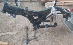
Progress so far.

stripped.1.jpg
Yes, going backwards to go forward! It does look like a perfect hole for a mid-drive motor, but it will also be great space for a controller and wiring


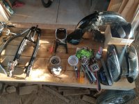
parts.jpg
The parts I'm keeping. Thinking about cutting out the top of the gas tank and hinging it with a latch for a glove box, maybe charger?


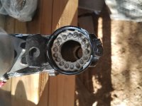
headset.jpg
Alright! Packing a headset with loose bearings, now this is familiar territory for me - like a giant bike!


re-pack.jpg

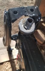
putting it back.jpg
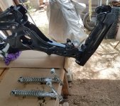
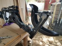
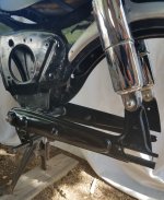
Some cool, leading link suspension with a pivot point behind the spring, and axle even further.


front end.jpg
and check out the size of the axle holes, yep they're different sizes, thought about a new wheel before I noticed that.
 
MACK said:
You were right on with my wheel at 22”, but from what I understand the controller is programmable and under features it lists “Configurable limit for motor current and battery current.” and in the spec’s it lists “Max Battery Current: Configurable.”
Yes, but the specification maxes are still maxes. So there is still a hard limit to system power, that you can change to various levels *below* that, but not above it. Whatever the specification says, that's the max. (or should be...you never really know for sure with some of these companies).

It's likely that this controller will supply plenty of power for your cruising needs---but you may want more power for acceleration (especially in traffic) or hill climbing. You may have to determine this experimentally since you've already got the stuff on the way.


The motor windings I learned about after I ordered, but what I (think I) ordered are their fast windings V3
“In terms of material, V3 motor has big trunking, uses more copper, with curve magnetic steel, and has highest efficiency and speed. It is the best option for enthusiastic fans pursuing perfect and high speed.”
Unfortunately none of that info is very useful to you. It's just marketing babble. :( Some of it does have meaning, but without specific numbers of both it and what it's comparing itself to, it's useless.

To break it down: "big trunking" might mean larger gauge phase wires, but without knowing how big, you can't know what kind of current you can safely put thru them. "more copper"...relative to what? "curve magnetic steel" *probably* means curved magnets, rather than flat ones, which affects how strongly they can be bonded to the rotor more than anything else. "highest efficiency"...relative to what? "speed"...means nothing--it's just a word "speed", by itself. :(


"Fast winding" doesn't mean anything unless you know how much faster it is supposed to be than some other winding, and that other winding has a speed stated, so you can calculate what "fast" means.

There is a motor spec called kV, which means RPM per volt. That means how many RPM the motor spins for every average volt provided by the controller.

So if you had a 72v battery that was at 72v, and you applied full throttle to the motor, it would be getting about 72v average on the motor windings, and if the motor was 9kV then it is 9RPM per volt, so 9 * 72 = 648RPM. You can then use RPM and wheel diameter to calculate MPH. That gives you the *unloaded* (offground) wheelspeed. Loaded, you get something like 80% of that, as long as you are applying enough power to actually go that speed (overcoming air resistance, etc). .8 * 648 = 518rpm.

The chart here:
https://endless-sphere.com/forums/viewtopic.php?t=16114
gives around 34MPH for that, with a 22" tire at 15.3RPM per MPH.

So to get 40MPH, assuming the 80% rule, you'd need to calculate for 50MPH unloaded, which is 765RPM. Then 765RPM at 72v would be 10.625, which is the kV needed in the motor to reach that speed.

Since the battery voltage isn't always 72v, then for part of the discharge curve it will be faster than that, and much of it it will be slower (because of voltage sag, etc). If you assume the 72v (20 cells in series) battery would be empty at 3.3v per cell, then 3.3v * 20s is 66v. When that close to empty, they'll also sag more, so let's say they sag down to 3v/cell, so you only get 60v. So to still really get 40MPH near empty, you'd actually need to calculate for 50mph unloaded at 60v, whcih is 765rpm / 60v = 12.75v/rpm for kV.


If the kV of the motor isn't that high, then you can either put it in a larger diameter wheel (probably not possible without extensively modifying the bike and changing it's handling), or you can use a higher voltage battery and controller.


If the goal is an even faster speed, you'll need an even higher kV motor. (or higher voltage battery and controller, or larger wheel).


With the configurable current limits in mind when I looked more closely at the motor specs these two
jumped out to me • Continious current:67A • Max current:80A Peak 140A
If those are the motor phase current specs, then you'll want to be sure to set the Kelly not to exceed them, unless you can cool the motor sufficiently.

If those are the controller phase current specs, then they dont' match the specs on the webpage, and you'd want to ask Kelly about that.

If those are the controller battery current specs, then that's what you've got to work with. ;)

For any of them you should ask to clarify what "max" and "peak" mean. Those *should* be the same, since it's also got a continuous rating. "continuous" *should* mean the maximum continuous it can handle forever. Then "peak" should mean what it can handle for X number of seconds (commonly ten). But they've got three different specs, so you should find out what limit each of them actually is, and how long each limit is for.

If they can't tell you, then you don't really have a definite idea what any of the terms mean, and so you don't really know what the part (motor or controller, whichever it is) can handle. Experimentation short of damaging things would then be the only real way to find out. :(


Battery advice helps, having read some of your posts on the idea of the heart of the system, it’s why I’m waiting till last for the battery, to be sure it’s the ‘right’ heart. I did have the # 72v 40Ah floating around in my head, I do want reasonable acceleration and to be ‘nice’ to the battery by not over draining it so I understand bigger can be better in this case, but I haven’t looked at the leaf or EIG cells yet, more research!
Figuring out the battery in something like this can be a PITA. ;)

One of the best things about the Leaf and EIG cells is they are bolt-together. So no worries about broken spot welds or other issues, and you can always replace cells if one has a problem later on. There are others out there like that too; but those are the only two I'm familiar with (I have EIGs, and have looked at Leaf cells a number of times as potential replacements sometime in the (far, I hope) future when it becomes necessary).
 
MACK said:
Yes, going backwards to go forward! It does look like a perfect hole for a mid-drive motor, but it will also be great space for a controller and wiring
Make sure the controller goes in the airflow. There is a lot of heat generated inside one, especially if you use regen braking. Box it up inside stuff and the heat stays in there too. :(


and check out the size of the axle holes, yep they're different sizes, thought about a new wheel before I noticed that.
If you need them to be the same size, and they are otherwise symmetrical, then you could find a spare part identical to the side that has the size you want, and swap it out for the size you don't.


Something else you want to do when modifying the rear end to hold the hubmotor is to make clamping torque plates for the dropouts. You don't want to just cut the existing dropouts open to make slots to slide the hubmotor axle into from the rear, even if it's axle flats are the same width as the existing slots. The frame isn't designed to resist axle torque, so you want to make torque plates to do that job.

There is a Torque Arm Picture Thread that has a lot of ideas on that, and some of the moped and MC conversions document what they did, too.
 
Update time:

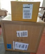
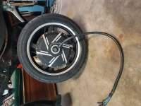
After being resigned to a long wait, I was greeted by boxes on the front porch yesterday!

woohoo.jpg


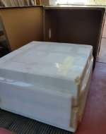
And quite the boxes they were, I was impressed with the packing for round the world shipping. After watching a few u-tube videos of parts reveal, I remember noticing on one - 'that's the end of the axle sticking out of the center of the box!'


packing.jpg


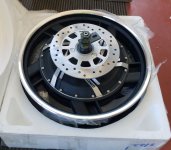
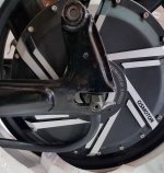
wheel.jpg


Not so on this one, I ordered it online from QS-Motor with the help of Robert Chen, as I've seen other references here to others interactions, most (all I've read?) have been positive, as was mine.(I have this thought that Robert Chen could be a position in a large factory filled by any number of people :wink: but hey if it works.)

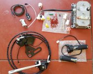
Then all the other parts of the kit:

parts w, Ccontroller.jpg


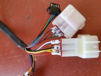
Nice to see labels on the wires, which correspond to the diagram.

controller.jpg


For reference this is the kit I ordered - but requested the 16" sized wheel instead of 17 http://www.qs-motor.com/product/17inch-4000w-hub-motor-electric-motorcycle-conversion-kits-max-speed-110kph/

All I've got for now, It's getting hot in the desert and I'm moving slow, so hopefully this week end I can get to work on the swing arm. I've looked at toque arms and understand the mechanics well and worked hard to fit the wheel so as not to need drastic modifications...we'll see how it goes :roll: defiantly some cutting

rear drop out.jpg


drop outs.jpg
 
Yes, I've had damaged axles from them peeking out of the box during shipping. :(


You probably are not planning to do so, but because a mechanical failure in this area can be so disastrous, then just to make sure this:
I've looked at toque arms and understand the mechanics well and worked hard to fit the wheel so as not to need drastic modifications...we'll see how it goes :roll: defiantly some cutting
doesn't mean you're going to just use those dropouts "raw", or perhaps with just the torque arm the motor comes with:

I would strongly recommend making clamping torque plates that bolt to the frame, to clamp those axles in.

Not doing so risks damage to the dropouts of the stamped-metal frame from axle rocking back and forth from accleration and braking, and then when it spins out (either because the frame gave out and rounded out, or because the axle snapped off from the stress) the motor wires twist and rip out and short, blowing up the controller.

The little torque arm the motor comes with is not necessarily sufficient, and those dropouts are not intended to resist torque, at all. The axle they normally hold doesn't exert any.


If you cut the dropouts open, then they can't resist torque even as well they might now (they can be pried open much easier). This is why a plate that bolts or clamps to the existing dropouts may be a good idea, if you have to cut the frame open at the rear of the dropouts to slide the motor in.
 
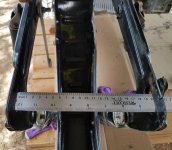
OK, back for an update. I think I've just about got the modifications finished for the attachment of the rear wheel.

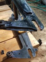
When I cut out the dropout to be able to attach the wheel I was please to confirm that they are a solid metal (3/8th) plate and not hollow like most of the frame :thumb:

cut out.jpg


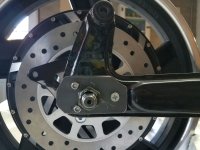
and of course the rear dropouts, like the front, had a larger axle diameter on the drive (left) side than the other??

drive side 1.jpg


The width was my big concern when ordering since I didn't want to get into cutting and widening the swing arm, so in that respect It worked out as there is just a minor stretch (couple mm) to slide it on, with the spacer and disk brake bracket in place.
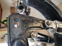
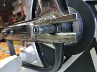
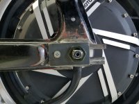
Cutting open the dropouts I knew would require reinforcement and I did a different version on each side.

There was quite a bit of room to fill on the drive side. I used 2 pieces of angle to shim it, and stick out further to make space for a bolt to pin them together.

2nd ver.jpg


The angle inside the dropout was a tight fit for the larger torque flat on this side. Then I cut a torque arm for the smaller flat further out on the axle out of a 1/4" steel plate, as reinforcement and a keeper for the axle. Still have to install a bolt between dropout extensions. (I needed to reacquaint my self with my welder as can be seen on the first (top) weld. It worked, just ugly!)

drive side.jpg

DS2.jpg


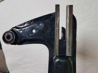
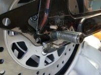
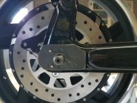
The brake side only needed a bottom shim to fit tight and square, but there was also the brake hanger that needed a little space from the bottom dropout. It will also need a hole drilled about in the middle of the drop out to capture the brake hanger.
To keep the dropout from opening under pressure I drilled a hole on the bottom and top of the opening and welded in bolts from the inside then ground them flat to fit with the brake hanger.
This side has a smaller torque flat, but it extends further out the axle so the plate I fashioned fits over the main torque flat and captures the rear bolts.


Brake side.jpg

BS1.jpg

BS2.jpg


That's where I'm at, a couple more holes to drill then the swing arm should be ready to reattach to the bike.

Next up on the list is getting a tire on the back wheel so it can attach to the (attached) swing arm!

Battery research still going on, want to cut the top off the gas tank to reattach with hinges for a glove box, then thinking about lights and a horn.
 
I'm back for an update:

Swing arm is finished, repainted and reattached!


re-attached.jpg

reconstruct.jpg


A new tire is on it's way, that will hopefully just fit right in side the wheel well. The tires that were on it were 3.5 x 16, and the new wheel spec's a 110-90 x16 which is 4.33" wide and too close for comfort for me to clear with out cutting out the frame. So, I've ordered a 100/90 x 16 which is just shy of 4" wide and should make it, and it's a 1"+ gain in diameter from the old wheel.

Now time to move ahead on the battery.

amberwolf said:
One of the best things about the Leaf and EIG cells is they are bolt-together. So no worries about broken spot welds or other issues, and you can always replace cells if one has a problem later on. There are others out there like that too; but those are the only two I'm familiar with (I have EIGs, and have looked at Leaf cells a number of times as potential replacements sometime in the (far, I hope) future when it becomes necessary).

Yes and yes, I think the Leaf cells are the way to go for me. Between being designed for vehicle power, the bolt together modules at 7.5V and 40 or 60Ah make for a lot fewer connections. I had looked at, understood and had an interest in the small cell battery building, but I new hooking up dozens and dozens of cells with tiny connections wasn't gonna happen for me (to the quality I would like it done). But the leaf cells, that's a battery I could finish with the reliability I want.

After pretty much deciding to go with the Leaf cells I was pleased to see Redmouse's update with his finished build. He built the same 72V battery I think I need, and he is using the exact controller I have. My hub motor is slightly larger (3.5KW/4KW) and the wheel is larger at 16". Now with his battery/controller power results it should help with this calculation-

amberwolf said:
Keep in mind that Kelly controllers measure current at the phases, not the battery. So the spec from their site: of 350A peak and 100A continuous is motor phase current. The actual battery current (and thus "system wattage") will be less by whatever factor that controller is setup for--if it's programmable, then you can change it within whatever range they've allowed. Not knowing that controller, I'd guess continous battery would be 50A or less; if so the system wattage would be 72v * 50A = 3600w. Controllers are not completely efficient, so you would get less than that at the motor. That might mean as little as 3000w or less, continous.

Redmouse reported a 90A draw from the battery (with setting maxed I assume), so the 72V * 90A = 6480W, should get 5500W or so in the end? (I know what they say when you ass-u-me, so I may be setting my self up here :roll: )

That's all I've got for now.
 
Progress!

tire on.jpg

Tire arrived and wasn't super hard to install, I went with the zip tie method. Hardest part was finding a 90deg. valve stem since there wasn't room for even the shortest straight one.

Since the tire was a little narrower then speced for the rim getting it seated took a little more than getting it on the rim. Some sun to warm it and a compression strap around the circumference, then a bit of bouncing did the trick to get it set.

Next to install it

doh.jpg


Doh! I found out why someone might want to cut off the fender, it would be a lot easier to install the wheel!

But with a little extra work it will go.


got it.jpg


After planning to mount the controller inside the open frame with the heat sink over the opening where the original air filter was, I realized I could make a cut out and insert it from the outside and expose more of the cooling fins, while still having all the connections contained, and easier to mount :D


outline.jpg


cooling fins.jpg


middle.jpg


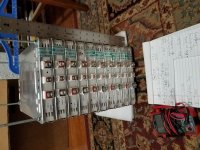
Leaf modules arrived for the battery build!


modules.jpg


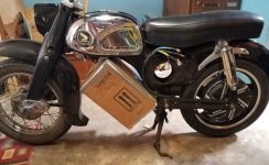
and I've built a cardboard mockup of the battery box I need to build to get an Idea of where it's gonna go.


battery box.jpg


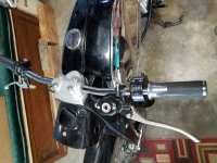
And the new handle bars arrived with some switches so it starting to really take shape.


handle bars.jpg
 
Wow the batteries look big for that frame! Will you build an enclosure for them?
Was it hard to find leaf cells? Can't wait to see your project finished.
 
vagosofron said:
Wow the batteries look big for that frame! Will you build an enclosure for them? Was it hard to find leaf cells?


Yeah they do! :shock: There is more clearance than it looks to the front fender...but not lots. It measures 9"x13"x14.5", that should fit the battery with space to get the wires out, hopefully!

One of my original goals was to NOT have a a big box or desktop computer hanging off the frame :lol:

Wanting it to be powerful enough to be road worthy and fun, I was thinking that while the frame is not the heaviest, it's defiantly not light, I decided on a 72V system. Then looking into batteries, I realized anything in 72V 40Ah range was going to be big and either pretty expensive, or really expensive.

Used leaf modules seem to be quite available now from a couple of suppliers in the US, (Greentecauto and Tech Direct). Mine were shipped from California for about $600.

With the separate modules I considered building two smaller batteries to hook up in series to get 72V, but the extra wiring/charging/monitoring seem a lot to me, and still 2 boxed shaped thing to fit.

After reading some of the battery threads I realized that if you were to open up the modules and re-wire them from 2s 2p to 4s 1p you could get the 72V but 1/2 the Ah with 5 modules. Understanding it was good but I didn't feel comfortable going that far for my fist battery build. As well as it's easier to be nice to a bigger battery to make it last longer.

So I'm still justifying a big box to my self. One can always cover it with a rounded shape or something, but than it's even bigger!

I plan to build a frame out of angle iron to attache it where the engine had, ideally keeping weight balance similar to the original for handling (hopefully at speed!)

My latest thought is to check with a sign printing shop that do full vehicle decals for advertising and such, to see what it would cost for them to basically make a sticker for the box that would make it look 3d with space age turbines or something??

When I ran the idea past my wife, she immediately laughed out loud.

Might be a winner then :wink:
 
MACK said:
One of my original goals was to NOT have a a big box or desktop computer hanging off the frame :lol:

You could make two narrow side panniers, very low around the rear axle, mounted to the frame (not the swingarm), each with half the batteries. The panniers can be anything on the outside. to match the look of the bike, just have to be solidly mounted on the frame, and hold the cells firmly.

Or part of them in panniers, and the rest in a much less "deep" structure where you have the "crate" now, that is easier to integrate into the look you're after.

It does make the wiring/etc more complicated, but it might be more in keeping with your plans for the look. You still only need one BMS; I'd use thicker wires for the balance-sense wires than usual, to compensate for the much longer length, and use the same length for all wires even if they're closer to the BMS than others.


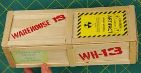
Another option is to actually make the box up as a wooden crate look, and burn Warehouse 13 and a crate number onto the sides. ;)
https://www.google.com/search?q=Warehouse+13+crate&tbm=isch
 

Attachments

  • index.jpg
    index.jpg
    14.2 KB · Views: 3,153
MACK said:
My latest thought is to check with a sign printing shop that do full vehicle decals for advertising and such, to see what it would cost for them to basically make a sticker for the box that would make it look 3d with space age turbines or something??

Great idea! Although I think a Steampunk theme would be much cooler and keeping with the "modern/vintage" vibe of your conversion.
NTDWM but something like this:

https://nl.123rf.com/photo_11106251...om-machines-and-tractors-old-rusty-machi.html

View attachment 1

https://nl.123rf.com/photo_11113470...om-machines-and-tractors-old-rusty-machi.html


Attachments

  • 111062512-steampunk-background-machine-parts-large-gears-and-chains-from-machines-and-tractors...jpg
    111062512-steampunk-background-machine-parts-large-gears-and-chains-from-machines-and-tractors...jpg
    306.2 KB · Views: 3,152
  • 111134702-steampunk-background-machine-parts-large-gears-and-chains-from-machines-and-tractors...jpg
    111134702-steampunk-background-machine-parts-large-gears-and-chains-from-machines-and-tractors...jpg
    303.3 KB · Views: 3,152
SlowCo said:
I think a Steampunk theme would be much cooler and keeping with the "modern/vintage" vibe of your conversion.

I think your probably right there, and to be honest after my wife laughed she said, 'well, maybe if was steampunk' :|. Cool pic's I think I even saw one with a leaf module and bike seat.


amberwolf said:
Another option is to actually make the box up as a wooden crate look, and burn Warehouse 13 and a crate number onto the sides.


:lol: :lol: Yes, I might need more than 1 cover to swap out depending on the occasion 8)
 
amberwolf said:
You still only need one BMS; I'd use thicker wires for the balance-sense wires than usual, to compensate for the much longer length, and use the same length for all wires even if they're closer to the BMS than others.


Good info, thanks. With these modules I figured I could get going with one big block, that I could split up at a later date, as a separate project/upgrade. I've thought about a V of sorts ??

Going for a keep it simple stupid approach at this point to keep from getting to overwhelmed with what I still need to learn to get it all hooked up and going. I'm seeing a light at the end of the tunnel but it's got a steep learning curve to get there! :pancake:

(not sure about the bunny pancake, but I think it covers my feelings!)
 
MACK said:
I'm seeing a light at the end of the tunnel but it's got a steep learning curve to get there! :pancake:
As long as you duck when you realize that is the oncoming train, you're all good. ;)


(not sure about the bunny pancake, but I think it covers my feelings!)
There's always this one, for when you can't wrap your head around something:
file.php

instead you can wrap it around your head. ;)

Or when you get completely tired of the whole thing:
file.php
 
amberwolf said:
instead you can wrap it around your head.

Yes I'm wrapped up in it!

what.jpg


Started working on the wiring for the lights and the rest of the 12V system. Most of it should fit inside the headlight shroud like the original so that's good. I plowed through the infamous Yuba Mundo Build and was equally parts inspired and overwhelmed with it all, so biting off small chunks at a time, 12V first.

wires!.jpg


wires 1.jpg


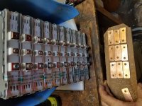
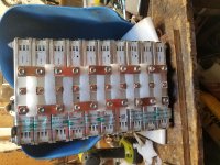
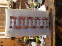
Battery went together well, after it was all compressed with end plates I cut the connectors out of 1/8" x 3/4" copper bar, cleaned them up and only ended up with 1 'almost'.


batt build -1.jpg


Added some insulation in between, then kept going.

batt build 1.jpg

batt build.jpg


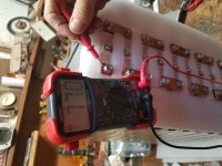
Before hooking the modules up I checked all the voltages and 6 were at 7.71 and 4 were at 7.72 so I thought it fine to join then all together at that point and pack voltage look good :thumb:

Battery.jpg


Now to get to work on the frame and box for the battery. Cheap 12V headlight that should fit in the original bracket, and turn signals are on there way through Amazon to finish the lighting system. Popped the chrome sides off the gas tank to prepare for cutting a lid, I think that's where the DC-DC converter is going to end up for the lights.

Onward!
 
Great work again :thumb:
If you use LED light "bulbs" you'll use less power/energy. So you could use a smaller dc-dc converter and have a slightly longer range.
 
These are the ones I'm using on the trike.
https://www.amazon.com/gp/product/B07JB9G57Q/ref=ppx_yo_dt_b_asin_title_o08_s00?ie=UTF8&psc=1
they are bright, daylight visible, white light, used in amber-lensed motorcycle signal housings. They'd work for tail/brake too, but I"m using LED strips for those.

They're completely enclosed in silicone so if water does get in the housing it shouldn't affect the electronics (unlke any of the other direct-replacement ones I've tried out).
 
SlowCo said:
If you use LED light "bulbs" you'll use less power/energy. So you could use a smaller dc-dc converter

Right, good point, less energy I understood but I didn't think it backwards enough to a smaller supply; and I'm learning space/weight is a key factor on small EV's, and good deal just swapping the bulb, I can still use these


yeah.jpg


amberwolf said:
These are the ones I'm using on the trike.

Perfect.


The headlight is proving to be a bit more of an issue.
MACK said:
Cheap 12V headlight that should fit in the original bracket...(is on it's way)

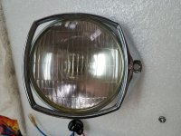
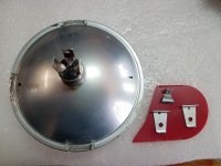
"Should" being the key word. The original headlight is a 5" square with two brackets one at 3 & 9 o'clock and a tilt adjust at the bottom. 5" is less common with most 5" lights - 5.75" actual size, and fitting in the original bracket was idea, so I was pleased to find one on Amazon for $14 with the same brackets, and the box looked like old leftover stock from a similar time.

It fit in and the brackets all lined up and it looked workable from the front except...

light front.jpg
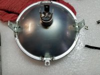
It was sideways! Same brackets 90deg off :(


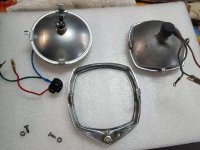
light !.jpg
These are the three oriented in their upright position.


So far the thought process in the last couple of days has been: 'Well does it really matter if the word TOP is at the top?' (YES)
I could see the middle part of the lens was focused differently (Taller vertically, and narrower), and that was true when I connected it to 12V in the garage as a test.
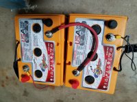
Speaking of which I just traded with a neighbor who was upgrading his camper's SLA AGM battery's to lithium and I got these


12V.jpg

Though maybe I could just use them on the bike instead of all this DC-DC converter bit.... :lol:

No I am excited to use them them to start to power the garage & shop lights with solar as well as the old on demand RV pump for the rainwater tanks! ( another post,I know).


So

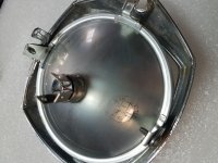
light back.jpg

Next thought was 'can I cut the spot welded tabs off leaving enough room to epoxy them back in the appropriate location-and would it hold?? doesn't seam like solder would help'

Now thinking more about LED, these are sealed beam so no swapping bulbs out so I might as well try a cut and paste and if it fails, even more reason to look further. :eek:
 
MACK said:
can still use these
yeah.jpg
Yes. I have very similar ones on the trike:
file.php

and what I was using before:
file.php


Next thought was 'can I cut the spot welded tabs off leaving enough room to epoxy them back in the appropriate location-and would it hold?? doesn't seam like solder would help'
Epoxy might work, if it isn't a type that will soften as the bulb heats up.

Tin/lead solder won't work, the metals are wrong and the strength is insufficient.

Brazing would work but it will overheat the light itself.

Spotwelding them on just like the factory did would be the best choice.

However you do it, cutting the tabs off carefully by dremmeling thru them or similar, between them and the bulb frame, rather than cutting them off "above" the weld, will allow you to reuse them more easily.
 
Back again with progress on the lights and switches.


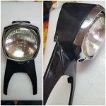
The bracket rearrangement on the head light is so far a success.


headl.jpg


brackets came off well enough, and I used a sharpie to mark where they needed to line up for mounting


epoxy.jpg


And it worked! kinda surprised myself - it was a slow, wobbly, reorienting wait for the 5 min set time for the epoxy. I did the 2 sides first and after it set up I mixed another round of epoxy to set the bottom tab and add another layer to the sides. Everything even lined up and fit back together.


headlight.jpg


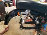
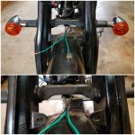
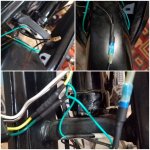
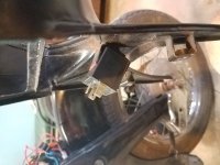
Now back to the wiring, threading the wires for the rear lights was a bit of a pain with the small enclosed channels that run along both sides of the inside of the fender. The right side had the signal as well as the tail light and without a frame grounding there was yet another wire for each.

wireing.jpg

At the tail light I ended up soldering the ground from the turn signal and the return to the base of the light fixture then wrapped the bracket with electrical tape before attaching to keep the grounding off the frame.

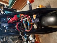
After much futzing with a pretty straightforward task it was rewarding to have the junction on the side wrap up quite neatly to leave room for the high power motor connection to all fit under the old battery cover.


wires back.jpg


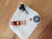
Probably a little overkill but I had the small copper lug hanging around I thought it would work for tying all the grounds together. Entertaining to make sure all was bolted to but insulated from the frame.

overkill.jpg


Now back to the front

front signal.1.jpg

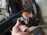
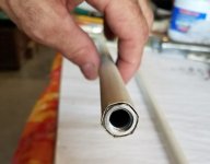
Found an old curtain rod that, with just a little flaring I was able to hammer in the nut from the front signal lights. There is hole on the forks where the crown attaches and was a perfect fit for the curtain rod. They really stamped into place so as not to turn and I cut the rod just short of the distance through the forks so the signals can be screwed in and held by compression.

signal.jpg

Next up I realized the bullet connectors were smaller than the ones I had but stretching one open enough to shove the other one in it made a junction of the grounds that was now the next size larger connector to fit mine, so it helped to clean up the hook up.

signal connect.jpg


Now for the rest of it

front wires.jpg

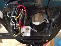
The wiring harness from the switch connected the horn, signals and hi/low beam, which I only wired high beam since headlight/taillight will be always on. The flasher relay that came with the switch and horn didn't cut it, (I think it's for led only) but a $12 one from the auto parts store did the trick and it works for LED, incandescent or a combination of both so I can swap out my signals and tail lights before the headlight.

blinker.jpg

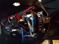
An old bracket adapted for the relay, and it all tucked in rather well after looking like a rats nest to me for so long.

shroud wires.jpg

After tying all the positive and negative leads together I hooked it up to a 12V battery for a test, and success!


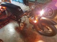
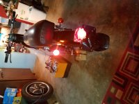
lights.jpg

lights back.jpg


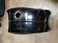
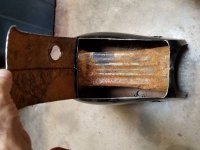
Boy the dremel with the little cut off blade is the bomb! Cut right through the tank with out loosing a lot of material.

Tank 1.jpg

Tank.jpg

Not quite as much room as it looked, but I think I can make a bit more.

That's all for now, a Cycle Analyst with shunt and a universal thumb throttle (regen)are on it's way from Grin Tech. and a 200A ANT BMS is on the way from AliExpress, so time to get to work on the battery box. Heat has broke/rain has arrived fortunately because I was having a hard time motivating to get welding outside in the heat.
 
FWIW, the turn signal flasher you have is the exact same one I've been using on CrazyBike2 and SB Cruiser for years. ;)


Kilz is a good paint to use inside the tank once you scrub out the worst rust.
 
Back
Top