upplastics
1 µW
- Joined
- Sep 20, 2020
- Messages
- 1
I'm pleased to confirm I've successfully created a design for a Honda Electric conversion on a 2004 Honda Ruckus. This project is not completely optimized, but I wanted to post it to get the word out and to see if any of you had ideas for improvement or could help with some of the parts I'm still looking at addressing. It is however, perfectly usable as is. I'm going to outline the design timeline so you can get an idea of why I ended up going this way and how it came to be.
1.Money. Cost is always a driver so this design kept that in mind the whole process. I had the very great opportunity of finding a completely rundown Ruckus for $50, so I had the perfect frame to start this project, and really an obligation at that price point , I already had a MY1020 motor 1800W and 30A controller from a previous project along with a 20,000mAh 48V lipo batter for testing the system initially so that's kinda what I went with. You can get MY1020 motors in various power levels fairly cheap and I've had good luck with them so that's what I started with.
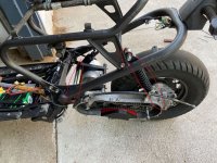
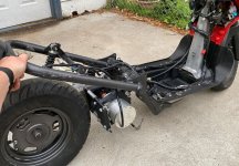
2.Thinking. So for thinking about the design, I knew there were lots of ways to go. Many people will tell you to just go with a hub motor in the back and find a way to mount it but the shock would be all wonky because you'd have to find a place to land it on the frame, also it would not look OEM which isn't very cool, and coolness definitely counts. Plus it keeps prying eyes at bay. Therefore I went with the same gearbox on the back wheel so I could reuse the existing shock and then mount the motor where the engine would be. This is called a mid-drive setup for those of you just getting into this. Also brakes are a bit thing and being able to use the same back tire with existing brakes is huge.
3. Teardown. Basically just rip the whole thing apart.
  I think all the wiring harnesses have connectors which is awesome. Take the gas tank out so you have that space back. The kickstand is actually attached to the bottom of the engine so that makes it a little difficult once you start getting into it. If you look at a Honda ruckus the back tire is held on with very little really. There is the main shock attached to the seat up top and the main swingarm bar usually runs through the engine. There is a bushing that is actually press fit into the engine housing, OEM number 11102-GEE-003. It's called an Engine Hanger.
 The main swingarm rod runs through that , one on the crankcase and one on the engine block. I bought a new one of those for the design because they are hard to reuse and put out of the engine block.
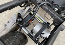
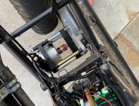
4. Design. Okay now that it's apart, how are you going to measure and design a way to hold the new motor in and couple it to the back gear. Hmmmmm. Well I've used this trick in the past. I actually took the crankcase apart and scanned it with a ruler for scale. This allowed me to outline the crankcase part in Fusion360 and scale the trace dimension using the ruler. This pops the whole trace to the correct scale. Very cool 8) . This would be very hard to dimension otherwise as the bolt holes are in very weird locations. You can see this trace in Scanned Crankcase file. I had to traverse the distance from the crankcase to where the engine hanger originally was so it will hold the new motor mount up on the swingarm of the frame. This could be hogged out of some aluminum or something but I thought, hey lets just mimic the swingarm rod itself and do that a few times with some long M8 bolts and some larger 20mm aluminum rod around those. I 3D printed the mounts for the motor and the engine hanger and the coupling to the crankcase. I was going to get these milled out at a machine shop, but $300... no thanks for now. I used protoplastic HTPLA and honestly its super strong, I was going to anneal it but didn't even do that yet, and it's been super strong. You can kinda see how this all came together in Fusion 360 in the Fusion files.

 I used lovejoy couplings to connect the output shaft, a 5/8" diameter, 4" long shaft. The motor output shaft is 12mm so I used a 12mm bore lovejoy on that side part number 6408K12 on McMaster-Carr I had to get a bearing to hold the shaft from moving in and out of the crankcase mount 3D printed part. I used part number 4768K5 to press fit into the 3D plastic. Note there is an improvement to this. The bearing kept getting pulled out of the plastic and a large washer to hold it in place or redesigning it to shoulder on one side would be better. There is a setscrew on that bearing that fixes the shaft from moving in and out of the mount. I started this design with chain so it would be a little easier without tensioning to start so you see a 28 tooth sprocket (#35 ANSI chain) on the motor direct drive side. So wait a minute...Doesn't the motor side usually have a small tooth sprocket... well yes usually, but I'm using the gearbox on this Honda Ruckus with has a reduction of 13.7 to 1. So every time you spin the back gear 13.7 times the wheel will move around once. The engine RPM on this motor is about 10,000 on the spec sheet, but can we trust that? NOOO, so lets measure it using a tach on the other gas Ruckus I very conveniently own.
 In RPM file you can see I measured 9483 RPM, soo....I guess we can trust it. Anywho that makes the Ruckus go about 40mph at 10,000 RPM. The MY1020 can only go about 4500 RPM, so dang we gunna be going SLOWWWW. Therefore we actually have to gear the opposite as usual. The crankcase only allows for about 3.5" clearance for a pulley, so 28 tooth is just as big as I can go.
5. Rear shaft. The rear gearset shaft is a lousy 17mm in diameter, which is super hard to find any pulleys or sprockets for. Therefore I had a 15 tooth sprocket bored out to 17mm and then double set screw to the shaft. I'm already moving on from this. I punched out the shaft and am going to machine it down to 5/8" so I can use standard pulleys and sprockets with a keyed shaft. I couldn't go any smaller than 15 tooth due to the 17mm limit. Therefore I'm using a 28:15 or 1.8666 ratio along with an existing 13.7:1 so a final gearset of 7.339:1. In theory with a 5000 RPM and 19" tire this would give us about 37 mph, but I only get 25mph so there are some obvious losses in the system or my motor is not getting up to RPM due to power constraints.
6. Results. Okay so on a 48V 20,000 mAh battery with a 220lb rider on a Honda Ruckus frame (large and bulky) with stock tires. I got about 7 or so miles of range with a top speed of 25mph. Obviously this isn't going to win any records at the moment, but hey I'm pretty happy. As far as I can tell nobody has really pulled this off OEM style like this yet. You could tie in the existing 12V blinkers and on/off switch. The controller and batteries easily fit underneath the plastic liner. Otherwise an upgraded battery could fit under the seat with ease. I've loved working on this project and will continue to do so. I plan on making a reddit post at some point along with a nice YouTube video.
7. Questions/Improvements. I know I can definitely upgrade to a MY1020 3000W motor with a Sabvoton 72150 controller or something to make sure I'm getting the full power of my Motor. Also I'm going to machine that back shaft and convert the chain to HTD pulleys probably 5m timing belts. This should run much quieter and I think I can get to a internal gear of around 3 instead of 1.8666 which should improve speed dramatically. I really want a spot welder to make my own batteries and have been looking at getting a kweld option but I'm having a hard time making the purchase. So... Hey what does the community recommend to go from here? Best controller? Where to get batteries? Design improvements? I'm curious what the community thinks!
1.Money. Cost is always a driver so this design kept that in mind the whole process. I had the very great opportunity of finding a completely rundown Ruckus for $50, so I had the perfect frame to start this project, and really an obligation at that price point
, I already had a MY1020 motor 1800W and 30A controller from a previous project along with a 20,000mAh 48V lipo batter for testing the system initially so that's kinda what I went with. You can get MY1020 motors in various power levels fairly cheap and I've had good luck with them so that's what I started with.2.Thinking. So for thinking about the design, I knew there were lots of ways to go. Many people will tell you to just go with a hub motor in the back and find a way to mount it but the shock would be all wonky because you'd have to find a place to land it on the frame, also it would not look OEM which isn't very cool, and coolness definitely counts. Plus it keeps prying eyes at bay. Therefore I went with the same gearbox on the back wheel so I could reuse the existing shock and then mount the motor where the engine would be. This is called a mid-drive setup for those of you just getting into this. Also brakes are a bit thing and being able to use the same back tire with existing brakes is huge.
3. Teardown.
Basically just rip the whole thing apart. I think all the wiring harnesses have connectors which is awesome. Take the gas tank out so you have that space back. The kickstand is actually attached to the bottom of the engine so that makes it a little difficult once you start getting into it. If you look at a Honda ruckus the back tire is held on with very little really. There is the main shock attached to the seat up top and the main swingarm bar usually runs through the engine. There is a bushing that is actually press fit into the engine housing, OEM number 11102-GEE-003. It's called an Engine Hanger. The main swingarm rod runs through that , one on the crankcase and one on the engine block. I bought a new one of those for the design because they are hard to reuse and put out of the engine block.4. Design. Okay now that it's apart, how are you going to measure and design a way to hold the new motor in and couple it to the back gear. Hmmmmm. Well I've used this trick in the past. I actually took the crankcase apart and scanned it with a ruler for scale. This allowed me to outline the crankcase part in Fusion360 and scale the trace dimension using the ruler. This pops the whole trace to the correct scale. Very cool 8)
. This would be very hard to dimension otherwise as the bolt holes are in very weird locations. You can see this trace in Scanned Crankcase file. I had to traverse the distance from the crankcase to where the engine hanger originally was so it will hold the new motor mount up on the swingarm of the frame. This could be hogged out of some aluminum or something but I thought, hey lets just mimic the swingarm rod itself and do that a few times with some long M8 bolts and some larger 20mm aluminum rod around those. I 3D printed the mounts for the motor and the engine hanger and the coupling to the crankcase. I was going to get these milled out at a machine shop, but $300... no thanks for now. I used protoplastic HTPLA and honestly its super strong, I was going to anneal it but didn't even do that yet, and it's been super strong. You can kinda see how this all came together in Fusion 360 in the Fusion files. I used lovejoy couplings to connect the output shaft, a 5/8" diameter, 4" long shaft. The motor output shaft is 12mm so I used a 12mm bore lovejoy on that side part number 6408K12 on McMaster-Carr I had to get a bearing to hold the shaft from moving in and out of the crankcase mount 3D printed part. I used part number 4768K5 to press fit into the 3D plastic. Note there is an improvement to this. The bearing kept getting pulled out of the plastic and a large washer to hold it in place or redesigning it to shoulder on one side would be better. There is a setscrew on that bearing that fixes the shaft from moving in and out of the mount. I started this design with chain so it would be a little easier without tensioning to start so you see a 28 tooth sprocket (#35 ANSI chain) on the motor direct drive side. So wait a minute...Doesn't the motor side usually have a small tooth sprocket... well yes usually, but I'm using the gearbox on this Honda Ruckus with has a reduction of 13.7 to 1. So every time you spin the back gear 13.7 times the wheel will move around once. The engine RPM on this motor is about 10,000 on the spec sheet, but can we trust that? NOOO, so lets measure it using a tach on the other gas Ruckus I very conveniently own. In RPM file you can see I measured 9483 RPM, soo....I guess we can trust it. Anywho that makes the Ruckus go about 40mph at 10,000 RPM. The MY1020 can only go about 4500 RPM, so dang we gunna be going SLOWWWW. Therefore we actually have to gear the opposite as usual. The crankcase only allows for about 3.5" clearance for a pulley, so 28 tooth is just as big as I can go. 5. Rear shaft.
The rear gearset shaft is a lousy 17mm in diameter, which is super hard to find any pulleys or sprockets for. Therefore I had a 15 tooth sprocket bored out to 17mm and then double set screw to the shaft. I'm already moving on from this. I punched out the shaft and am going to machine it down to 5/8" so I can use standard pulleys and sprockets with a keyed shaft. I couldn't go any smaller than 15 tooth due to the 17mm limit. Therefore I'm using a 28:15 or 1.8666 ratio along with an existing 13.7:1 so a final gearset of 7.339:1. In theory with a 5000 RPM and 19" tire this would give us about 37 mph, but I only get 25mph so there are some obvious losses in the system or my motor is not getting up to RPM due to power constraints. 6. Results. Okay so on a 48V 20,000 mAh battery with a 220lb rider on a Honda Ruckus frame (large and bulky) with stock tires. I got about 7 or so miles of range with a top speed of 25mph. Obviously this isn't going to win any records at the moment, but hey I'm pretty happy. As far as I can tell nobody has really pulled this off OEM style like this yet. You could tie in the existing 12V blinkers and on/off switch. The controller and batteries easily fit underneath the plastic liner. Otherwise an upgraded battery could fit under the seat with ease. I've loved working on this project and will continue to do so. I plan on making a reddit post at some point along with a nice YouTube video.
7. Questions/Improvements. I know I can definitely upgrade to a MY1020 3000W motor with a Sabvoton 72150 controller or something to make sure I'm getting the full power of my Motor. Also I'm going to machine that back shaft and convert the chain to HTD pulleys probably 5m timing belts. This should run much quieter and I think I can get to a internal gear of around 3 instead of 1.8666 which should improve speed dramatically. I really want a spot welder to make my own batteries and have been looking at getting a kweld option but I'm having a hard time making the purchase. So... Hey what does the community recommend to go from here? Best controller? Where to get batteries? Design improvements? I'm curious what the community thinks!