Yamaha XS400 conversion

TorgueRPM

100 W
Joined
Jan 9, 2019
Messages
171
Location
Milwaukee, Wisconsin, USA
I picked up an xs400 a couple months ago and have been stripping it down and restoring the brakes, forks, and frame in preparation to electrify it.

Parts:

Motor: Hubmonster 6-phase
Controllers: 2x Powervelocity NextGen 130v
Battery: 48s Toshiba SCiB LTO, total 2.2kWh, 110v nominal

I'm mostly waiting on the controllers, as there doesn't seem to be an ETA for those yet.
 

Attachments

  • 20200806_151910.jpg
    20200806_151910.jpg
    526.8 KB · Views: 2,806
That is a great bike to convert. Nice cruiser. Are you going to use the Hubmonster as mid drive or as hub in the rear wheel?
 
The Hubmonster will be in a middrive setup because I will never really hit anything over 55mph cruising around the city. I'm aiming to gear it at 1:2.5, for a top speed of around 50mph. Rear wheel torque could hit a nice 550 Nm :D

The drive sprocket is bolted on with 3 M8 12.9 grade bolts, which kinda makes me nervous with a potential 250Nm at the motor. There's a weird gap between the threading and the sprocket mount face which seems like it would make it easier to destroy the bolts, but it was only ever really meant for a disc brake.

Pencil for scale
 

Attachments

  • 20210210_184346.jpg
    20210210_184346.jpg
    297.4 KB · Views: 2,747
  • 20210210_185154.jpg
    20210210_185154.jpg
    233 KB · Views: 2,747
  • 20210210_184210.jpg
    20210210_184210.jpg
    229.4 KB · Views: 2,747
  • 20210210_184315.jpg
    20210210_184315.jpg
    277.1 KB · Views: 2,747
  • 20210210_184049.jpg
    20210210_184049.jpg
    202.7 KB · Views: 2,747
  • 20210210_184054.jpg
    20210210_184054.jpg
    235.6 KB · Views: 2,747
TorgueRPM said:
The drive sprocket is bolted on with 3 M8 12.9 grade bolts, which kinda makes me nervous with a potential 250Nm at the motor. There's a weird gap between the threading and the sprocket mount face which seems like it would make it easier to destroy the bolts, but it was only ever really meant for a disc brake.
Wouldn't hard braking have potentially a lot more force than the motor would create?
 
I don't think so, because eventually the rotor would lock up and the tire would skid. The torque would never go above the amount required to lock up the rear wheel. With a sprocket the torque can go higher.

I've decided not to worry about it, I'll just make sure the sprocket borehole fits the flange of the motor really well
 
I have ordered a 60t 428 sprocket from PBI and some motor mounting brackets from SendCutSend, and in the mean time I've been trying to get an idea about the bike's styling. I'm going for a cafe racer look, so I've chopped off part of the rear subframe and I'm currently mocking up the seat location.

One of the main design considerations for cafe racers is parallel lines, both in the frame and between the frame and the ground. With that in mind, I'm thinking of lengthening the rear shocks by 2-3cm to bring the rear up, which will also give more clearance between the wheel and the seat hoop that I will be welding on in place of the stuff I cut off. The trail of older cruisers seems big enough that my modifications won't decrease the bike's stability all that much.

I also just realized that some lower profile handlebars would look much better.
 

Attachments

  • chopped frame.jpg
    chopped frame.jpg
    314.7 KB · Views: 2,459
Raising the rear looks good and a flat(ter) handlebars would improve the looks and riding position. Maybe you can swap the footrests/mounts left <--> right so they are more rearwards. That would also improve the riding position, I think.
 
TorgueRPM said:
I don't think so, because eventually the rotor would lock up and the tire would skid. The torque would never go above the amount required to lock up the rear wheel. With a sprocket the torque can go higher.

I think, "amberwolf" is right.
As a general rule, in a street legal vehicle, brakes are ALWAYS stronger than the engine.

To your point above:
The torque of the engine will not go over the amount required to let the rear wheel spin...
 
I would agree that all of the brakes on a vehicle together are stronger than an engine, but I wouldn't say the rear brakes alone are.

When you brake, your weight shifts forward, decreasing peak friction between the wheel and the road and making it easier for the wheel to skid. But when you accelerate, your weight shifts towards the back of the vehicle, increasing friction. This is why I think that the forces on the bolts will be higher with a sprocket than a brake disk.
 
The sprocket, motor mounts, and chain came in. Today it was finally nice enough outside too take out my welder, so I welded together the motor mounts and lined everything up on the bike. The mounts will be lowered as much as possible in order to bring the chain line as close to the swing on pivot as possible to reduce suspension sag.

The first picture is the plan for the torque arms, which will be lined up with the flats on the axle, clamped, and then welded. This will let me line them up perfectly despite the fact that the flats on either side of the axle are not on the same planes.
 

Attachments

  • 20210303_163344.jpg
    20210303_163344.jpg
    146.8 KB · Views: 2,256
  • 20210303_163324.jpg
    20210303_163324.jpg
    259.1 KB · Views: 2,256
  • 20210303_163944.jpg
    20210303_163944.jpg
    301 KB · Views: 2,256
  • 20210303_163938.jpg
    20210303_163938.jpg
    287.5 KB · Views: 2,256
Nice progress :thumb:
Is the ventilation not turned around? Shouldn't it "scoop" the air up in the forward direction? Or does this orientation work better?
 
The ventilation blades are oriented to create a vacuum above the holes behind them as they spin, turning the whole motor into a centrifugal fan. This should pull air through the motor. John in CR has apparently used this idea with much success, check out his Hubmonster ventilation thread.
Once the motor is fully mounted down I will try using dry ice or some other method to visualize the airflow
 
FWIW, this is the same way most motor cooling fans operate (check out the alternator in most cars), as well as the way a vacuum motor system works.

It's a passive system that works well, and works better the faster the motor spins, so a motor running as a higher-RPM middrive will create more airflow (all other conditions the same) than the same one operating as a lower-RPM in-hub drive.

The

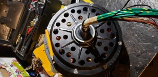
It also works better (in general) the larger the intake and outlet holes are (sometimes depending on their shape, especially at high air velocities), and the more fan blades there are (also more dependent on shape the higher the air velocity). In my limited experimentation, and observation of existing systems, larger inlet holes are more important than larger outlet holes at lower RPM, and larger outlet holes can be more important in higher RPM systems.

Part of that depends on the specifics of where the air needs to be directed inside as it comes into the inlet; in the case of an outrunner like these, it doesn't seem to matter as long as the stator support inside is "solid", and the intake holes are on the opposite cover from the outlet holes, so taht all airflow has to go past the coils and magnets on the way out on the other side. (this specific method and air path only directly cools the copper on the intake side of the stator, but copper has high thermal conductivity so the outlet side of the coils that are hotter will easily pass their heat over to the cooler intake side).

If the stator supports are "open" then air will flow more easily thru those than thru the outer airgap between magnets and stator (air generally flows more easily in a wider "hole"), and tend to bypass cooling the magnets or intake side copper, but will cool the outlet side copper on it's way out.

In this specific design, if the stator supports themselves are "aerodynamicized" ;) such that they create "lift" within the airflow path (vacuum on the outlet side relative to intake side) (they are rotating relative to the incoming air, even though they are not rotating relative to you, so this *may* be able to occur), it might increase the airflow slightly. I've never tested this.

(it would require clear sidecovers at the least plus a "smoke generator" to actually see how much air flows thru either path in the case of two paths being available).
 
I made some cut-outs for the motor mount so that it can sit lower. The open ends of the rectangular tube close to the lower frame tubes should help me weld the whole thing on securely. Also cut out the bottom of the tank, which should give me plenty of room to fit both controllers.
20210308_131724.jpg
20210308_134127.jpg
20210308_145407.jpg
 
Back
Top