1987 Yamaha FZR250

soyachips

1 W
Joined
Nov 3, 2012
Messages
52
1987 Yamaha FZR250 2KR
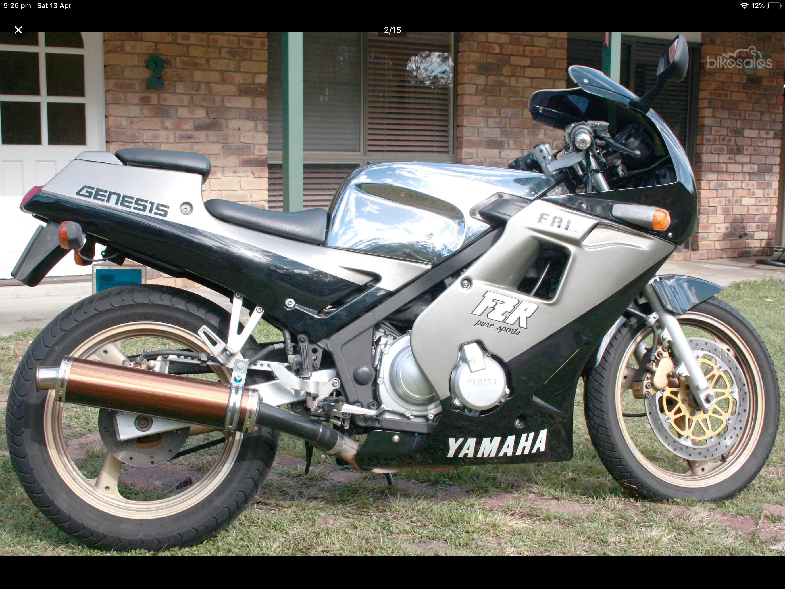
Motor: QS 273 6000W V3 hub motor 13.58Kv
Speed Controller: Kelly KLS7250H
Batteries: 23s1p 117Ah NMC prismatic cells (v1 Headway, v2 A123 20Ah pouch cells)

Top Speed: 110kmh
Range: 150-200km (to be confirmed)

I started this project in 2019 and having been keeping a build thread on another forum so there's a lot of posts to add here. The project is mostly complete but as these things go, they never really end :wink:

This was the donor bike:

file.php
 
So I originally thought about doing an electric cafe racer motorbike as there’s something appealing about the way they strip everything back to just the essentials and expose the way it all works but I struggled with how to make the batteries look good. In general, EV batteries don’t look that good so I then changed tack and started looking a bikes with fairings so I could hide them! I’m also keen to use a hub motor to simplify the conversion and leave plenty of space for everything else. The other thing I am trying to do is make this as easy as possible to get an engineer’s certificate for the conversion. I spoke to a few engineers about the project and a common theme was don’t touch the brake system otherwise you’ll need to do brake testing which could add another $3,000 :eek:

I had read good things about hub motors from QS Motor and they have a pretty extensive range of options. The bad thing was the hole pattern for mounting the brake rotor seemed non-standard so I thought I’d have to use the rotor that comes with the motor which is 220mm. So some more research to find bikes that use that size rotor on the rear and fairings to hide the batteries. The other thing was using a frame that has a cradle under the engine so when I take the the engine out it’s still structurally ok. Most new bikes seem to use the engine as part of the structure so that ruled out a whole lot of newer bikes. This really narrowed down the options so I finally settled on a late 80’s Yamaha FZR250 as my donor bike and proceeded to buy a swingarm and rear brake bits from a wrecker to do some prototyping.

Below are some photos of 3D printed custom axles to get everything fitting and the wheel centred and modifying the slots in the swingarm where the axle normally goes through into dropouts like on a push bike so I can get the motor in. On motorbikes the axle gets inserted through the swingarm into the wheel but on the QS hub motors the axle is fixed in the wheel.

file.php


file.php


file.php
 
Because the axle is built into the motor and needs to be held firm while the motor spins, there will be a lot of torque where the axle passes through the swingarm. To make this stronger I’m going to use solid blocks of aluminium? inside the swingarm. The tolerances need to be quite tight as there are acceleration and regen torque forces that need to be counteracted.

file.php
 
Here are some pics of the custom axle and motor. The axle flats are bigger than normal to give the torque arm/blocks more to hold.

file.php


file.php


file.php
 
Received the bike last week and started removing the ICE related bits that I won't be needing. One thing that I didn't expect to find was the coolant runs through the frame of the bike. There's a bolt on the lowest part of the frame used to drain the coolant out which I've done but now I'm wondering if the inside of the frame might start rusting without the coolant to protect it. Does anyone have any experience with this or thoughts on whether or not it could be an issue?

file.php


file.php


file.php


file.php
 
In my excitement to get started, I forgot to weigh the front and back to get the weight distribution of the original bike before taking it apart :eek:

So after putting everything except the seat and fairings back on and picking up a couple of bathroom scales from Bunnings, I now have the numbers

Front: 69.0 kg
Rear: 71.4 kg

file.php
 
Also put together a test battery pack using 24 x 15ah Headway cells to do some bench testing.

file.php


file.php


file.php
 
I struggled trying to get the controller to do the angle identification setup and control the motor but got there in the end. I did swap the positions of the hall sensor A and C wires in the connector so they matched the controller connector side. That didn't seem to fix it straight away but after running the setup step a few more times it eventually worked. Whenever the angle identification setup finishes it puts out a buzzer alarm code 3,2 which is for internal reset which isn't very intuitive. It might have been working a bit earlier as I didn't test the throttle every time it finished, thinking it hadn't worked because of the alarm!

[youtube]q5KbWbck08Q[/youtube]
 
One problem I've run into is the gap between the brake rotor and the motor is pretty small so the original brake caliper doesn't fit!

file.php


I contacted QS Motor and they recommended a few from their catalog that would work. Ended up getting this one in grey. I'll need to get a new mounting bracket made based on the original design and this new caliper.

file.php
 
Next step had some awesome help from Danny Ripperton machining the swingarm blocks that hold the hub motor axle. There's a slot on one side and pinch bolt to allow the blocks hold the axle flats as close/tightly as possible and to locate the blocks in the swingarm.

[youtube]G-SOqybw7E8[/youtube]

file.php


file.php
 
Put the new blocks into the existing swingarm, swapped the tyre over and got it all into the bike. Next step is to work out how to mount the batteries and controller inside the frame. Decided to push the bike home from the workshop and got some interesting shots on the way :D

file.php


file.php


file.php


file.php


file.php
 
OK so it's been way too long again! Quite a lot has happened but not nearly as much as I would have liked :)

I decided to build the battery box using V-slot aluminium extrusion which is used on 3D printers as this would allow me to play around and adjust the size of the box easily with basic tools and no welding. It's a modular system with lots of options for brackets, etc. that just screw together. I'm also using polycarbonate sheet which slots into the extrusion as the panels to keep the water out and allows inspection of everything.

I'm using 24 x 15ah and 24 x 10ah Headways cells to make up a pack. The 15ah and 10ah cells are paired up in parallel first then put together in series to make a 76.8V pack. The lengths of the cells are different so I ended up using aluminium spacers to make up the difference. Lots of cutting, drilling and filing to make the battery connectors but it's all together now and seems like it will work. At some point I will take it all apart, label everything so I know where everything goes and reassemble using carbon grease to get good contacts between all the critical surfaces. Also still need to attach the BMS wires to each cell somehow.

file.php


file.php


file.php
 
The other major update is on the rear brake caliper. Early on I did a lot of research to find a donor bike that I could reuse the original rear brake setup with the new hub motor. Doing lots of prototyping to make sure make sure it would all line up and fit ... so everything was going really well until I tried to put the original brake caliper over the brake rotor and it didn't fit because of the size of the hub motor!!! I contacted the QS Motor and they recommended an alternative that just fits. So the next step was to work out a new bracket.

I started off with timber to get a rough design then made some 3D printed prototypes. The final design had a slot that wasn't easy to make without having the right tools (e.g. a milling machine) so I've just sent it off to get machined through 3DHubs. You can upload a 3D model to their site and get an instant quote in different materials and finishes which is very cool. I'm using Aluminum 7075-T6 which is a bit stronger and will be bead blasted then anodized black. The great thing about CNC machining and 3D printing is that complexity comes for free, the machine doesn't care what crazy design you come up with. It just has to move around a bit more! Anyway very excited to see what the final part looks like and will post some pics when it arrives.

file.php


file.php


file.php


file.php


file.php
 
Looks very nice, I considered using the original rear caliper support bar too but didn't find a neat way to do it.

How much did you have to pay for the 3DHubs part? I considered using them for my axlemounts too but the price I was qouted was hilariously expensive.
 
Anders said:
How much did you have to pay for the 3DHubs part? I considered using them for my axlemounts too but the price I was qouted was hilariously expensive.

Yeah it wasn't cheap, I paid AUD370 which included a premium for fast turnaround. I can't remember how much extra that was though.
 
I'm trying to get the bike ready to show at EV Expo in Sydney this weekend so got some more work done yesterday. Made a plate to mount a waterproof box to hold things like 12V battery, contactor, fuse and other bits and pieces. Most of the high voltage stuff is in and wired up so its mostly the 12V bits to get it running. I've had trouble finding a wiring diagram for the bike so it may take some time to work out. After the expo I'll take it all apart again and do things properly before it's really done so this is kind of a practice run putting it all together!

file.php


file.php


file.php
 
OK it’s been a while again so there are a few updates. The EV Expo was great to be part of. Lots of interesting conversations with people and great to see all the other conversions people have done. I didn’t quite manage to get it running for the show but it was all together at least. It didn’t take too long after the show to get it running but like everything on this project there’s been a lot of two steps forward one step back! I killed a relay I was using to turn on the controller, also damaged a relay in one of the BMS modules I’m using so had to send that off to get repaired. Also spent quite a bit of time getting the 12V system working and cleaning up the wiring harness to only have the wires still being used. Last weekend went for my first ride on the bike and adjusted some of the controller settings. Overall the testing went really well so I’m pretty close to getting the certifying engineer to do brake testing except that one of the cell groups died and I now have to get some replacement cells :shock: so probably a couple of weeks before they arrive. Will post some videos of the test rides soon.
 
After the last lot of testing there was a fair bit of work to do getting ready for brake testing and inspection. Replace dead battery cells, wire in the emergency cutoff switch, replace oil in forks and add spacers, etc so after all that the bike pretty much looks the same but a lot has happened! Last Thursday took the bike out to the drag strip at Eastern Creek where an engineer put some instrumentation on the bike and did a series of brake tests. Everything went well so I just need to provide some documentation on the conversion and get it officially weighed then it should be good to get certified. Looking forward to getting it on the road so I can play around with the speed controller settings to get it dialled in.

file.php
 
My biggest constraint is range which at the moment is only 25km. The 10Ah cells I bought on eBay and the 15Ah cells I got second hand. I’m not even sure if the 10Ah cells are original Headway cells or some other brand! I’ve got a couple of CellLog 8S from my previous project that I’m using to log rides and work out which are the weakest cells. So one by one I’m replacing the weakest cells but I’m going to run out of spares soon. So my dilemma is do I keep buying replacement cells and slowly fixing the weakest link or is it better to save up and replace the lot. If I do that I’d like to use all 15Ah cells and possibly go to 24s3p instead of 24s2p. The bigger capacity should handle the current draw better and increase my range to around 50km assuming the current cells have lost some capacity. Or do I go to a new chemistry altogether? Lots to think about.

Here’s a log of the middle 8 cells in the pack during one of the test rides clearly showing cell 8 dropping away before the others.

file.php
 
I recently added a brake lever to the bike to control the amount of regenerative braking to use. Previously I was just using the percentage setting in the Kelly controller to control the amount but it was either just right at lower speeds and not enough at higher speeds or vice versa. This way I can control it myself. Just need to adjust the amount of air in the hydraulic reservoir to make it feel like the other brake lever.

file.php
 
Also I've managed to get some A123 20Ah cells to upgrade my battery pack. These looks like pretty amazing cells compared to the Headways so I'm really looking forward to getting these in the bike and seeing how they go. I built some cardboard boxes to try out different configurations and although I could do a 23s3p pack, I've decided to go with a 26s2p pack instead. The 2p pack can be made with all the cells stacked neatly together whereas the 3p pack would have to be an odd shaped box with the pack split into 3 sections. Plus I have enough cells for the 2p version already. Here are some photos of a test box to check everything fits into the box and the box fits into the bike!

file.php


file.php


file.php
 
Back
Top