Tandem Skateboard / Scooter

Joined
Jan 5, 2012
Messages
73
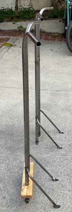
This is a double skateboard with handles. Hence blurred between skateboard or scooter. We have had an unpowered version for years, but now need a little assist to get around.IMG_0490.jpg
 
The Speaker Guy said:
This is a double skateboard with handles. Hence blurred between skateboard or scooter. We have had an unpowered version for years, but now need a little assist to get around.

Are you asking if one exists, or for recommendations for one?

If you're intending to show one you've got or made, then whatever media you've got didnt' attach to the post.
 
I guess I will edit top post as needed. This post joins at 3/4 of the way through the build

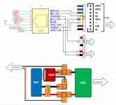
Wiring notes - Left Handlebar
XLR 1 red pos, 2 black neg, 3 white power
Brake blue 5v, green sig, yellow gnd


XLR is in the handlebar end. I put the male there as it fit inside the 7/8" tube. {ins 1 and 2 are the power. Pin 3 in charger cable is shorted to V+, and this is used an an ENABLE signal to the Arduino and power supply.

Brake is a hall effect thumb throttle, on the left handlebar.

A brief story about the hall sensor. I'm an engineer. I know what a Hall sensor is. I was not aware that they were standard operating procedure for ebike throttles. Makes sense in hindsight. I thought the throttle was a potentiometer! As I had intended on reversing the polarity of the brake, I had to revise my plan.
 
Arduino Shield
  • Battery Input / Charge Output - Fused at 5A
  • Charge input - 3 - pin XLR to Shield via wires through handlebar. Includes sense pin to allow Arduino to detect charger is plugged in.
  • LTC7103 105V 2.3A synchronous buck. Power for Arduino, RGB LEDs, cooling fan.
  • Plugs directly to Arduino UNO format
  • Includes level shifter so works with 5V or 3.3V Arduinos
  • Op amp buffers for throttle and brake signal. Brake is inverted, two signals summed, so 2.5V at rest, 5V full throttle, 0V for full brake.
  • Uses JST SM connectors for IO from box to scooter.
  • Uses RJ-45 connector for control, UART, throttle signals to BMS and VESC
  • Uses 5mm screw terminal for battery in / charge output
 
LOL, AmberWolf, you jumped in so fast. Thanks for the interest. I was just starting on the post, and have edited. I guess I like posts where number 1 is conclusion, then follows build log in chronological order. But as you may see below, I am jumping around.

A build log is a great place to keep notes instead of a random post it on my messy desk.
 
The Speaker Guy said:
LOL, AmberWolf, you jumped in so fast. Thanks for the interest. I was just starting on the post, and have edited. I guess I like posts where number 1 is conclusion, then follows build log in chronological order. But as you may see below, I am jumping around.

A build log is a great place to keep notes instead of a random post it on my messy desk.

Yes, that's kinda what I use mine for. :oops: Sorry for jumping in so quick; am home sick in bed but stuck awake (yet brain not fully "functional") so on the computer trying not to be bored to death. :lol:
 
Regarding throttles, there are potentiometer throttles; two common good full-grip ones are Magura and Domino. A fair number of mobility devices still use pot throttles, too. There are also cable-operated versions. (also of hall versions). Grip throttles can be converted to thumb in a number of ways, if necessary.

Since you're using an MCU, you can easily reverse the response of a throttle by inverting it's interpreted output voltage, and even offset it's range, so you get "zero" for full throttle and "max" for no throttle.

In hardware you can reverse the response of a throttle by using an op-amp to invert the voltage it outputs, and if necessary a second op-amp to offset the range back down to a "zero" reference point.
 
Now back for earlier stuff
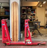
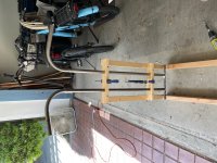
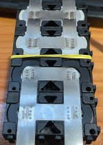
IMG_0476.jpg

The foreground is the current scooter, vertically behind it is the new deck.

Current scooter is all Flintstonian propulsion. It does have LED lights, fixed intensity, powered by three AA batteries

Objectives for new scooter:
  • Electrical assist to get us about 10 miles round trip
  • Programmable LED lighting
  • Less obtrusive handlebar assembly

The old scooter had cutouts for wheel clearance in turns, but that was to be avoided. We also wanted larger diameter wheels, so the ride height had to increase:
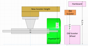
Ride Height.png

Old scooter wheel was ABEC 11 Centrax 77, but new is going to use 97mm Flywheels which I had laying around. I figured a 1/2" increase in ride height would be ok, especially as our knees get less pushing work due to electric motor assist.
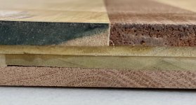
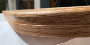
IMG_0165.jpg
This shows the stackup of the deck lamination. Top is 7mm maple and mahogany. Middle are 3.5mm polar on 45° bias to top layer (not 90° like typical plywood). Bottom is red oak, about 7mm. Glue up was Titebond III.

I built a steam bender to allow laminating the perimeter of the deck with 3 plys of 6mm x 37mm oak. I tried to do this with mahogany but it would not take the 75mm radius at the rear of the deck.
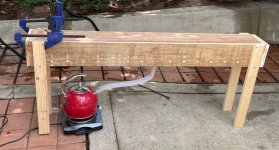

IMG_0209.jpg

The steam bender is made from cedar fence boards, with a tea kettle and a hot plate.

Here are the laminations being glued up with a clamping jig I built.
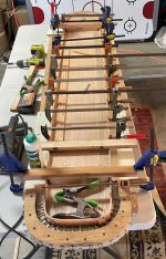
IMG_0275.jpg
 
The handlebars are made from 7/8" (22mm) diameter steel tubing, just a generic carbon steel, nothing too fancy.

IMG_0475.jpg


A jig was made to ensure everything came out aligned while welding
IMG_0471.jpg

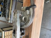
This is the manual tubing bender I used, I believe I got this from Summit Racing about 10 years ago
IMG_0454.jpg

Cross bars and struts are 1/2" diameter (12.7mm) carbon steel. This was welded with HF 110V/220V MIG welder
 
The edge of the board has a dado routed in to allow the RGB LEDs to be recessed. This is shown with 3 coats of Watco Danish clear on red oak. I masked the deck and sprayed the dado with Gorilla spray adhesive to ensure the self adhesive LED strip really stuck.

IMG_0311.jpg

Below is a preliminary program intended for 4th of July in USA.

IMG_0442.jpg
 
I started the battery this week. This project is now about 6 months old, and I seem to have forgotten the objectives along the way. I optimized the drive train for 12S, and bought Molicel P45 to do 12S4P battery pack. As I started to wire the balance leads to the BMS, I somehow bought a Daly 14S 100A dumb (not smart) BMS. I looked around, and could find no guidance on the use of 14S BMS with a 12S pack. My hunch is I would be dead in the water if I tried to do this.

I considered getting the right BMS, but then noticed 12S was a particularly weird quantity. Most of the Li+ BMS were 13S which is indeed closer to 48V nominal.

So I modified the 12S pack to accept a 2S addition as the 12S pack was already assembled and welded.

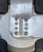
I did have trouble with my Sunkko737G. I had used it before with 18650 and thin strips, but it would not dent the 0.2mm material I got for this pack. I ended up getting an 11000mAH handheld unit from Amazon. This works very well, but you have to let the leads cool down a bit.
IMG_0542.jpg
IMG_0543.jpg
 
I reckoned this was definitely a dual motor application, but had an issue: I did not want cutouts, so narrower trucks were needed. Also, narrower are a bit stronger, a good idea when two people ride one skateboard. The original scooter used 137mm Indy trucks IIRC, and never had a problem. It used #8 screws, those broke a couple times. For this build I went with M5 hardware.

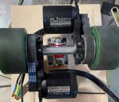
With dual 6374 motors and narrow trucks, a typical dual motor setup would not work. I could do one motor front truck and one motor rear truck, but figured that may have an issue with torque steering. So I decided to put both motors onto the rear truck, one in front of the kingpin, and one behind.

Trucks are Caliber III Raked 7.5".

IMG_0178.jpg

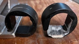
To get the mounts as far up the truck as I needed there needed to be some manual filing. This took about an hour to get a good fit.

IMG_0173.jpg
 
amberwolf said:
8>< snip
Since you're using an MCU, you can easily reverse the response of a throttle by inverting it's interpreted output voltage, and even offset it's range, so you get "zero" for full throttle and "max" for no throttle.

In hardware you can reverse the response of a throttle by using an op-amp to invert the voltage it outputs, and if necessary a second op-amp to offset the range back down to a "zero" reference point.

I did not want the throttle control to be dependent on the MCU. I did an op amp inverter, see the schematic. GMTA. The Arduino does monitor the voltage at the throttle, when it drops below 2.5V the rear red LEDs go from 20% to 80% intensity, a brake light!
 
This is the rear wiring. I have a signal for an NTC, but am not going to add this at this time. The fan is a 5V, 80mmx10mm, it will run all the time when the motor is on, and also when charging. I am not sure when i will stop it charging as the Arduino does not know when charger releases. Perhaps a 12 hour timer or so.

Rear Wiring.png
 
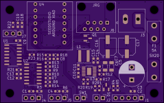
I had to revise the PCB. There is a mistake where I used a pin SCL that is also used as A5 on another pin, but they are actually connected in common on the UNO. The other PCBs which use UNO form factor don't have an analog pin on SCL as an option, so ... doh!

but the main reason for the revision: I went 0 for 3 on properly soldering the QFN devices on the LTC7103. So I reverted to a technology I know. I changed to LT8620, which is 65V, 2A (compared to the 105V 2.5A LTC7103). For this build 65V is OK, but the 105V was attractive for the future.

The new revision has following changes:
- Change LTC7103 to LT8620
- Change mechanical from an Arduino Uno Shield to a Seeeduino XIAO PCB mount module
* This goes from a 5V ATMEGA328P to a SAMD21 at 3.3V
* This has only 14 pins, with 12 GPIO, the design uses 10 of these
- Add 100µF electrolytic cap to the VBAT node
- Remove the polyfuse

Shield II Top PCB.png
 
This new PCB will be smaller, it is 75% of the previous area, with a max height of 15mm including the XIAO module. Previous stack up was 25mm. In fact, I can mount the large electrolytic horizontally and reduce the height to 12mm, but we'll see ...

The SAMD21 based Arduinos have 3.3V IO voltages, but that was already addressed in the in previous versions.

Other mods
- changing the brake signal to be only the brake output measurement, not the combined throttle and brake signal
- Adding 100Ω series resistor and extra 2.2µF bypass cap on the op amp power supply. This will filter noise above 700Hz or so, hence rejecting the ripple from the DC-DC converter LT8620
 
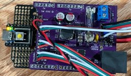
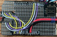
While awaiting new PCB, I have made a breadboard adapter from Rev II UNO Shield to Seeduino Xiao. I also will use an external 5V supply.

I also learned (a bit late) that the Xiao has an issue which periodically requires a hard reset before it can be programmed. That is the tactile switch taped to the metal shield on the Xiao. Much easier than squeaking in a pair of tweezers.

IMG_0590.jpg
IMG_0591.jpg
 
larsb said:
Love this quirky build, i wish it was mine :thumb:

Won’t the turning radius be huge? Like not possible to stick to one lane when doing a turn?

I've tried the board, it can do a U turn in about 24 foot diameter (12 foot {4m} radius). The trucks are kept somewhat loose, and they are positive raked trucks with 50° baseplate, giving a bit more turn per unit leaning.

https://www.muirskate.com/longboard/trucks/74061/caliber-3-184mm-raked-raw-50-degree-longboard-skateboard-trucks
 
Back
Top