Electric conversion of a 1984 Honda CM450

harrisonpatm

10 kW
Joined
Aug 8, 2022
Messages
821
I was attracted to YouTube videos of electric motorcycle conversions and I kept thinking that it seemed doable, even for my inexperienced talents. So when I came across an old Honda with a dead engine going for $150, I went for it. This was mid-May of this year, about 4 months ago.

IMG_20220525_194206.jpg

Engine was dead, but that didn't matter, and frame was good. I stripped it to pieces, which was my first pleasant surprise, because I was actually able to do it completely in one day by myself with no specialty tools. That's when I got confident and started ordering parts, and taking night classes at YouTube university to brush up on all the skills I would need.

-QS273 8000W-continuous-rated hub motor on an 16-in rim, Kenda Challenger tire
-APT96600 400 amp BLDC motor controller. It has its pros and cons, but mostly I got it because it came with the motor and I had to start somewhere. It's not terrible, but I'll find a different one for the next conversion.

IMG_20220805_112129.jpg

-Battery! I wanted to go LiFePO4, even though it's heavier than Li-Ion, because I'm not an experienced rider and I went for safety, longevity, and temp range (I live in Michigan and might be using this in late fall and early spring) over weight and power. Went with 32650s from Battery Hookup, 12p24s to get that 72v range, just over 5kwh. I picked a JKBMS 200A for it's price point and relatively good reviews online. Daly was another option, but much pricier. We'll see if this one lasts. Battery weight with cables and everything was about 110 pounds, still lighter than the engine was. I don't weld, so I found a welder who was able to make an aluminum case for it that mounted to the frame in the same spot the engine was. If the brackets held the 175-lb engine, they'll hold the battery just fine.

IMG_20220720_154415.jpg
IMG_20220824_183644.jpg

I use a 400-amp contactor, a 200-amp shunt to read amperage off the battery during riding, and a 350-amp breaker for the power train cabling. BMS rated for 200 amps continuous, the controller is rated for 600 amps, the motor is rated for about 130 amps continuous and 250 amps peak... I should be good. Spoiler alert, it does run, but I would love feedback from the forum on how well I selected, rated and built all my components. Who wants to place bets on which component fails first?!?

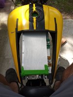
I cut the bottom of the fuel tank to make room for electronics. Then when the controller arrived, much larger than expected, I cut a hole out of the top as well. Oh well.
IMG_20220807_145619.jpg

For charging, I don't actually have an AC charger yet, but it is planned, either purchase or assemble. For now, I set up 2ea 240w solar panls on the south side of my house. Series connected for now, at about 66Voc, connected to the MPT-7210 boost charge converter to bump it to motorcycle battery voltage. This gives me 4-8 amps at a time, which means I can fully charge the battery in about 10-14 hours of direct sunlight (2-3 days?) This is totally fine for now, I'm not riding miles every day, don't need to charge it every day. This is just going to be my commuter to work 2-3 miles a day, plus joy riding. My future upgrade plan is to upgrade my house's small off-grid battery bank to 48V and use a proper, better, true MPPT controller to collect sunlight at all times, not just when I have the bike plugged in. Then I can treat that as my bike's reservoir, and use a boost converter to tap into the 48V bank to charge my 72v bike; faster, more regularly (better for long-term battery life), and more convenient.

I could go into a lot more details on every little thing, but I'll let pictures speak for themselves. Let me know if you have any comments or feedback. I also have plenty more to do. Namely, need to find a better way to cover up the controller. If anyone is thinking about doing it, I say go for it. This was a surprisingly achievable project.
IMG_20220826_150651.jpgIMG_20220826_150657.jpgIMG_20220826_150736.jpgIMG_20220827_134741.jpg

P.S. The biggest mistake I made was picking a relatively heavy bike. Next time, I'm going smaller and lighter. Smaller battery needed, smaller motor, smaller controller, cheaper, ect...

Checking out the competition...
IMG_20220827_152327.jpg
 

Attachments

  • IMG_20220807_145605.jpg
    IMG_20220807_145605.jpg
    356.3 KB · Views: 889
Sorry guys, I'm a new member and I'm now seeing that this post belongs in the E-scooter/E-Motorcycle section, not ebike. Perhaps a moderator could move it?
 
Couple months of use, and I wanted to update, for anyone else referencing the post for their own builds. I commute 5 miles round trip every day. So far I'm still limited to direct solar charging, which is a lovely idea in concept but means I'm highly dependent on the weather if I want to plan a longer outing. I've ordered an AC charger to remedy that, and I am still slowly working on the stationary solar backup battery in my free time. Then I'll have a proper solar-powered motorcycle that I can charge much more regularly and conveniently.

The 32650 cells I picked were perfectly ok, but next time I will try to find something that can handle higher discharge rates without voltage sag. Under normal driving conditions, I see on my panel mounted voltmeter a sag of around 2-3 percent. This goes up to 4-5 percent sag when I have to accelerate to 60-80kmh. Then when I really have to floor it, to overcome traffic or go up a steep hill, I see an 8-10 percent sag. The voltage always rebounds back up easily enough, and I rarely have to pull the full 200-300 amps to make it happen, but in a perfect world, I'd rather not have that much sag.

Top cruising speed, easily maintained without stressing the battery, is 50-55mph no problem. I can use the boost mode to get up to 65-70 for short periods of time, as long as I keep them short. Range on a full charge is 45-55 miles depending on how hard and fast I'm going. Bike weight is about 350 pounds, I weigh 200.

One more ask, would a moderator possibly be able to move this post to the E-Motorcycle Builds thread? I mistakenly posted in the wrong section as a newbie, and I have since learned the error of my ways, but I don't think I can move the post over myself.
Edit: Thank you!
 
Nice! Did you have to modify your swingarm at all to fit the QS motor? And how was the process of swapping out the rear drum brake for a disc brake?
 
Nice! Did you have to modify your swingarm at all to fit the QS motor?
Not much. A slot gets cut out of the back so qs273 can slide in without removing the axle. The original axle is bigger than the qs273 by 1-2mm, so I made a couple shims to keep the axle from moving vertically within the swingarm. I did not bend the swingarm, but I did use about 3-8mm worth of spacers, also provided by qsmotor. I used the qs-provided torque arms, tightened the axle closed with a lock washers, then drilled through the nut and the axle to insert cotter pins on both sides. I have had zero loosening or spinout.


And how was the process of swapping out the rear drum brake for a disc brake?
Not well enough that I would recommend what i did. You can purchase disc brake calipers and adapters that fit your axle size. And use the torque bar from the drum brake to fix it relative to the axle. It technical works on my setup, but not great; you can only expect so much from slapping on aftermarket parts. On the plus side, I rarely use it. I've had several emergency stop from 50mph, and I did them with the original front drum brake. Plus I have regen braking from the rear wheel. So I don't miss the rear brake, but if I did it again, I'd find a rear swingarm that already has rear disc brakes on it.

If you look into the physics of motorcycle riding, the front wheel does the majority of stopping power anyway.

20230609_055914.jpg
20230609_055840.jpg
 
I used the qs-provided torque arms, tightened the axle closed with a lock washers, then drilled through the nut and the axle to insert cotter pins on both sides.
Nice, yeah I'd want to use a cotter pin just like my CB550 stock axle did to prevent loosening.

I'm thinking of using regen for rear wheel breaking as well - it seems like it would do just as good of a job as the old drum brakes (without the maintenance) and also like you said, braking power overwhelmingly comes from the front brake.

What do you have the regen hooked up to? The old rear brake pedal or something on the handlebars?
 
What do you have the regen hooked up to? The old rear brake pedal or something on the handlebars?
I got the apt96600, and it has an automatic regen function. When i roll back on the throttle, regen engages. No input from me needed. I messed with the settings until I found an amount of rear wheel braking that would bring me to a stop at a red light or stop sign, gently but firmly. I said that I rarely use the rear disc brake? I also don't even use the front brake much, only when finishing a stop or in an emergency.

My controller may or may not have variable regen capability, I'm not sure, it was difficult to figure out. But I've found that I don't feel I need it in my case, so I stopped worrying about it.
 
Had a small malfunction today, the throttle stopped responding mid ride and I was able to safely pull over to the side of the road to diagnose. This is why you should always carry tools with you! Battery's BMS reported no errors, charge was over 70%, I was still getting power to the converter for lights and accessories, and the contactor was responding to on and off. I noticed that turning the throttle, I could still hear a bit of an electronic whine coming from the controller, and my current display was reporting spikes of 5-30 amps, but not wheel movement. After some fiddling, I found the error lights on the controller indicating a hall sensor error. Luckily QS motor gives you two redundant hall sensors, so after swapping that connection, the bike responded normally and I was able to get home.

In a couple weeks I have to put the bike away for cold weather, so it might be a good time to open up the motor and see if there's anything I can do in there. Should I be worried about potential corrosion that caused the issue? Or do hall sensors sometimes just fail? Nice that QS motor builds it with two.

I will say, I've ridden this bike about 5000 miles so far, and this is the first time I've had a drivetrain issue. And yet I was still able to (at least for now) fix it and keep going in less than 10 minutes. Sure beats any other vehicle I've had so far.
 
Could be a brocken leg from the hall sensor. I have a hubmotor with nearly the same mileage, which had the same issue. The cables inside the motor to the hall sensor put stress on the legs.

I have another motor which is now 10years old and has done 30000miles without issues from the hall sensores, even not after melting the phase wires
 
Last edited:
It's more likely to be a connection problem than an actual sensor problem. That could include a broken leg if they're not supported by a board, etc., or glued down, but is more often a crimp issue at the connector, or solder at the sensor, etc.

Sensors generally fail from environmental (water, heat) problems, or damage to wiring that shorts them to excessive voltage.

If there is no shielding between the phase and hall cabling, there could be induced currents into the hall wiring that can cause voltage spikes, and if htose are high enough it could damage the halls....but this could also feed into the controller and damage it, too--so this is the least likely cause of hall failures where a second set works.
 
I checked the original hall sensors' resistance and it does appear to be a broken connection on one of them. Likely a broken leg as mentioned earlier. Possibly in the cable run. Hopefully not water damage. There is shielding between the phase and hall cables. In a week or two the motor is coming off for the winter anyway. I've already ordered replacement hall sensors, as well as varnish. If I'm going to be taking the hub apart, I can hopefully mitigate any current water damage. If there's no water damage and just a failed sensor, I can replace all of the halls, and varnish the whole thing anyway if I'm going to the trouble of having it open, to prevent future damage.

Not going to open it yet, as the backup halls are working for now, I don't have replacement ones to replace them anyway, there's two more weeks of decent riding weather,
 
Could be a brocken leg from the hall sensor. I have a hubmotor with nearly the same mileage, which had the same issue. The cables insife the motor to the hall sensor put stress on the legs.
This is encouraging, thanks. I don't mind the work of taking it apart and doing that repair, I just hope that it isn't full of water.
 
I checked the original hall sensors' resistance and it does appear to be a broken connection on one of them. Likely a broken leg as mentioned earlier. Possibly in the cable run. Hopefully not water damage. There is shielding between the phase and hall cables. In a week or two the motor is coming off for the winter anyway. I've already ordered replacement hall sensors, as well as varnish. If I'm going to be taking the hub apart, I can hopefully mitigate any current water damage. If there's no water damage and just a failed sensor, I can replace all of the halls, and varnish the whole thing anyway if I'm going to the trouble of having it open, to prevent future damage.

Not going to open it yet, as the backup halls are working for now, I don't have replacement ones to replace them anyway, there's two more weeks of decent riding weather,

First time seeing your build thread 👍
Not sure how I missed it.

Since you’re opening your hub, it would be a smart idea to change out the bearings. Since you’re varnishing, you might as well do everything you can while it’s open. The phase wire size is probably good for your situation because I don’t believe you’re pulling more than 150 A right? I would imagine your motor barely gets warm being the big QS 273 ⚡⚡⚡

And thats great that QS puts in two sets of hall sensors, right!

For curing the varnish do you have an oven?
 
The phase wire size is probably good for your situation because I don’t believe you’re pulling more than 150 A right?
It's fine, and anyway it's a hub motor so I'm limited by the axle hole.

Thanks for the bearing idea, I'll check those out.

I don't have an oven. I ordered EL 601 sprayon, and it'll be better than nothing.
 
I have a QS 260 40H 5kW hub and feed it with up to 630pA and up to 280battery amps, I only upgraded the phase wires to 16mm² and added a thermal sensor. ,Before I melted the awg5 13.3mm² phase wires with 27kw uphill, without temp sensor.

The new QS273 60H 10kW hub has the wires not through the axle. So the wires in this motor are 25mm²
 
Disassembled the bike for the winter, and I wanted to quick get the motor open to satisfy my curiosity and see whether there was water damage, Luckily for me there wasn't! So the hall failure is either a broken wire somewhere down the cable line, or an actual failed sensor.
IMG_20231116_144339.jpg
@Eastwood , I think I'm going to just leave the bearings alone. I don't have a ton of tools (like a bearing puller) and I don't want to damage something trying to fix something that isn't broken, I have a bad track record of that.

This blue stuff, that acted as an extra seal. When I reassemble, I'll want to put another layer down of something to reseal. What can I use? I was thinking engine gasket seal, something like permatex. And I do already have varnish ready for reassembly. Can I spray a layer on the magnets too, or should I just leave them alone?
IMG_20231116_144353.jpg


Last thing. I have a plan on how to remove the stator from the rotor to replace the sensors (they haven't arrived in the mail yet, and I have all winter to do the job, so I'm not in a hurry). To put it back on, is there a method that will avoid the tremendous snap back into place? I'm concerned about cracking one of the magnets on its way back in. I've worked on small motors plenty before, like 500-1000w, and they're scary enough when I reassemble.
 
@Eastwood , I think I'm going to just leave the bearings alone. I don't have a ton of tools (like a bearing puller) and I don't want to damage something trying to fix something that isn't broken, I have a bad track record of that.

Well, it would be better to pull the bearing off the shaft and install it in the side cover for reassembly. In my experience it’s harder to reassemble the side plate covers if the bearing is stuck on the shaft. Sometimes we get lucky when we open the motors and the bearing stays in the side plate cover. That being said, you might damage the dust seal on the bearing when using the gear puller, so you might as well change it out.


@Eastwood
This blue stuff, that acted as an extra seal. When I reassemble, I'll want to put another layer down of something to reseal. What can I use? I was thinking engine gasket seal, something like permatex. And I do already have varnish ready for reassembly. Can I spray a layer on the magnets too, or should I just leave them alone?

Before applying any more sealant on the side cover, I would clean it back to the bare metal. You could try a plastic putty knife or even using a fresh razor blade if you stay flush. Or you could just go to some high grit sandpaper and take it down to bare metal.
I’m normally start with a “fresh” razor blade and clean off the stubborn parts with high grit sandpaper.

For sealant I’ve always used high temp RTV silicone as its meant for metal to metal contact.
J-B Weld 31314 High Temperature RTV Silicone Gasket Maker
Amazon.com

Or you use the non high temp vervison of permeated as it’s good for 450°, which is plenty.
Permatex 81158 Black Silicone Adhesive Sealant, 3 oz. Tube, Pack of 1 Amazon.com


And yes, you can spray the magnets as you want to because they can rust as well. Just make sure when you’re spraying the varnish, you spray extremely thin layers, 5 or so very thin layers you should be good. The varnish you have will not block the magnetic field so no worries there. When curing the varnish, you wanna make sure it’s baked properly, because it takes a long time for it to truly cure. Even after you properly, bake it, I would still leave the motor apart for a couple of weeks just to let it completely cure. Mainly because the reassembly will scratch the varnish when the stator and rotor slam back together from the magnetic force.


Last thing. I have a plan on how to remove the stator from the rotor to replace the sensors (they haven't arrived in the mail yet, and I have all winter to do the job, so I'm not in a hurry). To put it back on, is there a method that will avoid the tremendous snap back into place? I'm concerned about cracking one of the magnets on its way back in. I've worked on small motors plenty before, like 500-1000w, and they're scary enough when I reassemble.

Removing the stator is pretty simple since the hub is in a wheel. You simply remove one side cover and leave that side toward the ground so the axle is touching the floor. Then remove all of the bolts of the side plate cover on the corresponding side. all you have to do is step on both edges of the tire and the stator will pop right out. Just never ever put your fingers near the magnets when doing this or reassembly, very dangerous.

For reassembly, you do the same. You stand on both ends of the tire, then holding the stator by shaft on the discharge wire side, and slowly lower the stator into the magnets. That’s with that side cover already installed. You’ll need to prop something under the wheel on both sides that you’re standing on so it’s elevated off the ground. I just use some old couch cushions. And yes, it will be a loud bang when it snaps together it’s quite nerve-racking the first time you do it but it’s really not too bad as long as you make sure to keep everything straight. To prevent scratching the varnish with reassembly, I used plain printer paper that I wrapped around the stator and pulled the paper out once it was re-assembled. I have pictures on my build thread you could look through. I wouldn’t worry about cracking a magnet because everything will go back in so flush as there’s not much allowance. Just make sure the stator doesn’t try to jerk sideways into the magnets, but it shouldn’t as long as you’re holding it straight.

The varnishing detail start on page 4
 
Last edited:
You can absolutely avoid a large bang and the massive axial thrust that you might put on the bearing if you let it slam back together. Get a large 3 jaw puller, hook the arms to the rotor and set the tip in the dimple on the end of the motor shaft/axle. If there isn't a dimple just add one with a small drill bit. Then you just slowly unscrew the main bolt and let the stator pull itself back in.
If the air gap is big enough you can slide some thin cardboard inbetween the stator and rotor to prevent scratching, I have used cereal boxes for this.
I can almost, but not quite, picture what you're describing. Are you saying that the puller jaws are on the outside of the rotor, in the direction of travel of the stator/shaft moving it's way back it?

I don't actually have a puller that large, but you've at least given me ideas. And maybe I can get a puller, which would also be used if I do need to change the bearings eventually.
 
You can absolutely avoid a large bang

But why are you trying to avoid the bang since it doesn’t cause any damage? It’s just the side plate smacking the hub motor housing. It’s two steal parts that are completely flush smacking together so there’s no damage. I’ve done the method with using a gear puller to slowly lower the stator into place but felt like it was a waste of time since there’s no issue with the loud bang.
 
But why are you trying to avoid the bang since it doesn’t cause any damage? It’s just the side plate smacking the hub motor housing. It’s two steal parts that are completely flush smacking together so there’s no damage. I’ve done the method with using a gear puller to slowly lower the stator into place but felt like it was a waste of time since there’s no issue with the loud bang.
Once with a smaller 500w BLDC hoverboard motor, the stator slammed into the motor at a slight angle and popped a magnet out of its position. Once, out of about 200 times ive done it on those sized motors, so the chance is quite small, but something I'm aware of. Alternatively, when talking about 2 large and heavy pieces of metal slamming into each other, there's a concern of so much moving mass getting out of control and causing injuries, as you point out:
Just never ever put your fingers near the magnets when doing this or reassembly, very dangerous.

However, you're not wrong:
And yes, it will be a loud bang when it snaps together it’s quite nerve-racking the first time you do it but it’s really not too bad
I'm sure I can manage and I'll be used to it when I do it once. I just haven't done it before on something this size, those magnets are scary strong.
 
Back
Top