JP spot-welder, FET-switched, timed adj. pulse

Has anyone used the IRLB3034pbf fets? They're cheap, have a low RDS-on, and run very cool under high amp loads. Rated for 40V and 195A. These were the unbreakable super-fets used in airsoft and RC solid state switches. I ordered 10, along with a programable pulse timer board to goof around with. Maybe I'll luck out and accidentally end up with a spot welder.
 
SwampDonkey said:
Has anyone used the IRLB3034pbf fets? They're cheap, have a low RDS-on, and run very cool under high amp loads. Rated for 40V and 195A. These were the unbreakable super-fets used in airsoft and RC solid state switches. I ordered 10, along with a programable pulse timer board to goof around with. Maybe I'll luck out and accidentally end up with a spot welder.

The current and avalanche energy specs look pretty similar to the IRF1324PBF which I chose. I guess if you need more voltage they'd be a good option. But IRF1324PBF is cheaper.
 
so im looking to use the jp welder timer and make a suped up power board for copper welding. 24*1324 fets, in a double row, was thinking to use pure copper busbars, as opposed to aluminium, as i can solder to it. or better to use crimp lugs and plenty of auminium?
any forseen issues with getting the fets syncronised?
plan to power it with 3 *140ah sla's from a telephone exchange..
the aim is to weld up to 0.2mm copper sheet.
 
ridethelightning said:
so im looking to use the jp welder timer and make a suped up power board for copper welding. 24*1324 fets, in a double row, was thinking to use pure copper busbars, as opposed to aluminium, as i can solder to it. or better to use crimp lugs and plenty of auminium?
any forseen issues with getting the fets syncronised?
plan to power it with 3 *140ah sla's from a telephone exchange..
the aim is to weld up to 0.2mm copper sheet.
so it looks like it might be a good idea to use a 2 stage switching config for using more mosfets.
to be sure there is enough current to drive all the gates.
i ordered some 20 irf1324s 7pbf fets, but im wondering if the one used in the kwelder, FDB0105N407L would be better?
they seem to be able to take more current and are 40v fets, not 24volt.
 
riba2233 said:
Yes, they should be slightly better, but are more costly.
Thanks riba. they seem to be roughly the same price currently on element14. shame i already got the irf1324s ones :|
i can return them but may lose some cash doing it.
when i saw the the fets on the kwelder thread and assumed they were the 1324s.
some difference in critical specs for the irf1324s-7pbf and FDB0105N407L fets, respectively, as follows:
single pulse avalanch energy 230 mj vs 1109 mj
max pulse drain current 1640A vs 2540 A

next step will be to find the best way to attach the body of them to copper bus bar. I thought of solderig them on 0.2mm copper foil first, (as i thought id need way too much heat to get them on the crazy 6mm*40 mm copper bar i have 8) ) then solder or screw the foil to the bus bar some way.

other option would be to make a clamping bar that screws down and presses them to the bus bar without solder.
 
spinningmagnets said:
Ridethelightning, when soldering components onto a thick copper bus, you might consider a DIY RSU made from a 1000W microwave oven transformer...

thanks for that!
shame i tossed my mot welder :( might have to find a new one, or start playing with some necro 25r cells to provide the power source, or use one of the 6kw44v dc server supplies i found :D
quote from your rsu thread-

"The solder is the most resistant part in the electrical-circuit path, so...the heat originates at the solder and radiates outward (if one probe is on the cell-tip, and one probe is on the copper bus). When you stop applying current, the copper bus will then pull heat away from the freshly soldered joint. "

this would translate to one probe on the fet, other on the bus, and melt the solder between. ofcourse id experiment first some old fets to see how hot they get. i guesse the more power you can get in short time the better too.

i also wonder if the resistance of the solder would be an argument for just clamping the fets down, as that might actually have lower resistance than using the solder...maybe thats why riba also likes that option? :)
 
I embark on diy CD spot welder.. My goal is to make welder for very small wires and plates to medium sized.. And to control how much voltage or current (for both pulses seperat) and offcourse all 3 times controlled. Big lcd screen to display programed presents and grafs.. That will be done with arduino.
Capacitors I was looking o buy 6x 3400F @ 2.85V...
That should be more than enough power.
To control U... It will be 3 capacitor in series up to 8.5V
an seperat part same configuration.. Aka puls 1 can be 3V and puls 2 can be 5V.
To achieve repeatable pressure on metal.. I intend to use 2 nema 14 motors and controled with arduino by load cell..
I come here for power electric part.. So mybe anyone would be interested to cooperate on power board..
I belive I've seen someone who is interested in same.
Anyway... Bom will be about 250€ max.. (arduino 10.7cm screen is 60€, 6x capacitor 100€ and.. Components.. Still unknown price.)
Give me your thoughts and opinions.. Note that I allredy decided on big screen and do it one and good no that čing čong quality...
Prices on such machines are like 3000€+
Regards :)
 
Just completed this mosfet welder build. Question, is it best to locate the Schottky diode closer to the negative side of the battery, then how I currently have it next to the positive side? Battery is directly under the wood.

Thank you.

diode placement_s.jpg
 
True, working on spring version for equal pressure.
Any ideas on Shockey diode placement closer to negative side?
 
Hi guys,

first I want to thank you all for all the informations provided here... it's really very helpful for understanding the spot welding topic and issues that arise while building and using it... I learned a lot!
I would like to build a spot welder with a bit higher voltage (20V) so I could get more Joules of energy out of it. I have 7 pieces of 25V 47.000uF capacitors (0.329F total) and I would like to charge them with a laptop adapter (19.5V DC). I already bought 20 mosfets (IRF1404), which I hope will be up to the job. Now I'm not sure what types of the following parts do I need for that and how many:
- freewheeling diode (Schottky): I'm guessing 3 pieces of VS-100BGQ015 in parallel should do, right?
- TVS diodes: I'm thinking 10 pieces just in case, because there's gonna be a lot of Amps. I'm just having a problem choosing the right type... I saw 5KP13A was used many times, but I'm not sure whether it's ratings will be ok for my needs. Probably not. Maybe 5KP22A would be more appropriate?
- what kind of FET driver should I use and how many? Can I wire all the fets to the same driver? I was planing to use an optocoupler (PC817) instead of the driver, but I don't know if that's a good idea...

Can anyone help me choosing the components? I wouldn't wanna build it and then burn it at first spot weld...
Thank you in advance :)
 
Hi Guys,
I'm new here, but have found this particlar thread to be incredibly helpful in building a battery spot welder. I'll try to post some pictures soon.

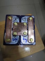
Main welding power source is a 12V 710CCA car battery.
Used ten IRF3205 mosfets on a 1"x1/4" aluminium flat bar.
An Aduino Nano is at the heart of things.
Probes are about 40cm long 8awg stranded wire. The electrodes are made from some copper tube, with the 8awg soldered in one end, and some very short copper nail in the business end.
Flyback is (hopefully) being taken care of by two 30SQ045 schottky diodes from the drain back to the battery positive.
Also have five 1.5KE TVS diodes between source and drain. Not sure if these are needed or correct, but they don't seem to hurt ;)

So a footswitch starts the process. A short pulse (10% of the main pulse is) is fired, followed by a 100ms delay, followed by the main welding pulse, which can be set between 1-40ms by a simple potentiometer. A TC4420 mosfet driver controls the gates (driven with a 12V supply). I have one ten ohm resistor on each gate.

Messed around a bit with the first pulse (between 10-20%). No really any noticeable difference. But definitely a diferent when i turned it off. So it's set at 0% now. Also the delay between the pulses didn't make any notecable difference, so just left it at 100ms. Not using the arduino timers to control it, just simple delayMicrosecond() and delay() functions. Accurate enough I think.

Welding a 0.15mm nickel strip to an 18650 is very consistent. Timing is 7ms. After about 50 repeated welds within a couple of seconds of each other the mosfets and the aluminium bar were up to around 40 degree C (ambient temp around 30 degrees). The 8awg wires were a little warm so will be changing them to 6awg as and when the wire arrives.

Over this weekend it has done over 1000 welds and all is still good, but I'm sure that there's room for improvement.

We back to back tested it against a couple of cheap ebay specials and there was no comparison. The ebay versions were all quite inconsistent with anything over 0.12mm nickel strip.

Next plan is to implement an 'auto' feature, but I hope that's pretty simple. I'm not a fan of the footswitch. Just lazy perhaps :)

Anyway, just thought that I'd share my experience seeing as I trawled this thread pretty heavily during making the welder.

Cheers,

Matt.
 
Back
Top