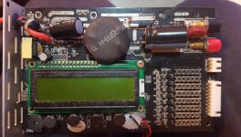
icharger failures, detail how your icharger failed

My first Post in this forum. :D Well I was stupid enough to connect my icharger 208b to my ebike battery not thinking of the 32V Voltage limit. It has been sitting around for about a year now. Before throwing it away I decided to check the insides again.
The input voltage regulator was heating up when i connected the charger to the input voltage. So I guess that thing is gone.
Pin 3 is connected to Ground
Pin 4,5 somehow to Vin
Pin 2 somehow to the output voltage.

Long story short. It seems to be an LM2587S ADJ
I don't think it is a fixed Voltage because somewhere after PIN 2 there is a "voltage diveder" with two resistors. I couldn't exactly measure the values but the fixed voltages would connect directly to Vout as Pin 2 is the feedback line.
In the progress of desoldering i sadly messed up the pad of the pcb for pin 2. Maybe I can fix it somehow. First I'll order one these.

@FalconFour: Maybe it helps if you plan to fix your 3010b.
 
Oh wow. I never imagined trying that one... it's a step-up (boost) converter. Unless they're abusing the design (seems unlikely given the complexity of these things), that doesn't seem right. How'd you come upon that... is there a slightly less abridged version of long story short? :)

I've still got my 3010b, but I suspect there's more the matter with it than just the regulator, now (initially, it was chosen as a donor because I bonked it with a brief spike of reverse-polarity across 16-or-so NiMH cells with ambiguous markings - it would no longer "start", it'd just "battery check" and then reboot itself). So I think the 3010b sacrificed itself to save my 208b, now I have two perfectly working 208b's - one with a neat white-on-black LCD display (after I couldn't get the OLED replacement working).

Curious to see what you find with that replacement. Sadly, can't say I expect miracles, but bring up voltage slowly with a controlled supply to find out! If it's the wrong chip, you could easily smoke the 5v control guts if you give it 12v and expect it to regulate down. Start it off at 5 volts and, say, 500mA, on a bench supply, to keep from giving it too much magic to smoke with. :) Before you try bringing it up any higher, measure the voltage at ... eh, hmm, the electrolytic cap on mine was on its side under the LCD - that's what you'd probe to see what voltage the logic was getting. It should be 5v.

If you see it following your supply voltage, that's bad mojo, back off it... you can start to let out magic smoke around 7v on a 5v circuit, so that should be enough room to tinker around and see if it's following your voltage or not (it should not, it should stay 5v). :)

BUT THEN AGAIN...
The MOSFET gate drivers run at 12v :? :? :? But the supply goes down to 4.5v. So maybe, it just might be a boost after all, in some weird way to create a dual voltage output. Hmmmm...
 
FalconFour said:
ying that one... it's a step-up (boost) converter. Un

o maybe, it just might be a boost after all, in some weird way to create a dual voltage output. Hmmmm...

IDK aboot the Icharger..

but my Powerlabs ( 6s-32s, 1000w-5,400 watts, 1-4 channel, ) are certainly both a buck AND boost converter, each with their own ( differnet) efficiencies. Easily calculatable.
 
I actually managed to get the 208b running again yesterday. It was a nightmare getting the display desoldered. I was wise enough to order a spare display, so i kind of destroyed the whole display and the pins and desoldered them one by one.
Replacing the voltage regulator was also a pain and i really don't know if the whole surface is soldered to the pcb but i hope it won't get too hot.

I started off searching for all kinds of voltage regulators with the voltage input range of the icharger (3-32V) which didn't get me too far. I searched through a lot of datasheets but in most of them the design example was not even close to what I could figure out from the icharger,
In the end it helped me that I could hardly see a Logo carved into the IC what appered to be National Seminconductor.
So I thought if i can identify the logo maybe i can make something else visible.
First i took a couple of picture with different lighting. I imagined that i could at least read something like "LM" written on it.
Final approach was toothpaste. I could not identify all numbers right away but after googling a little i narrowed it down.
I first thought of the fixed 5V version but as i stated before PIN 2 would be connected directly to the Output Voltage.

I guess there was a lot of luck to it. Seems somebody also made a mistake not to mill the ic a little deeper :wink:
 
Holy crap, that is incredible.

I'm going to buy one, then, and see if it powers my 3010b back up. If it does that, then it's a solution for the over-volt failures, at least (because putting the 3010b's original working reg into my 208b is what repaired it from an over-voltage event).

Indeed, a bit of a mistake not fully sanding off that part number, as all of mine so far have been dutifully sanded off. haha. Awesome break, there!

Oh, and the trick to desoldering the screen is a hot high powered iron (I use a TS100 with Ralim's firmware, a 6s LiPo, and a proper D24 tip, not the conical crap they include), and to add extra solder and sweep the pins in groups, keeping it level but lifting/slightly bending one edge at a time, sweep across to level out the tension, heat and lift a group on the other edge, back and forth, until eventually it detaches and you can keep it all molten to remove. Then, solder-wick the excess solder away (always cut the wick before applying it so it doesn't burn more flux in the unused portions!), and you'll have a reusable screen ;) That is... if you don't accidentally pull too hard and rip pads off the board (my case, lol).
 
Okay, back again (man, this is a saga, isn't it?). I finally bought, received, and installed the LM2587S - specifically, here: https://www.ebay.com/itm/324069759884

Guess what? It worked. :shock:

However, due to the existing damage that led the charger to being relegated to parts anyway (had reverse polarity at reasonably high voltage applied to the output), I ended up on a rollercoaster ride: first, somehow bridged pins on the LM' chip though I carefully avoided that... had a false start of "oh well, didn't work", started listing it for parts... realized the bridged pins, fixed it, it booted up, great! Noticed that U7 was getting quite hot with no operation running... ohmed it out, found it near shorted, broke it off. Then the charger booted and seemed to work (would charge & discharge!). But only if input < output voltage - that is, it'd work in boost, but not buck mode. In my curiosity, I played with slowly raising input > output while charging... aaaaand it fried itself again.

This time, it just has "seizures on the floor" whenever voltage is applied, making sparking and sputtering sounds, with the display flickering and literally saying "AAAAAA....AAAAAA" in waves on the screen. How uh... :oops: yikes. Never seen a piece of gear screaming in pain so clearly...

So I finally put it out of its misery... listed it on eBay for parts for $20 and very clearly "not working" :lol:

Oh well. We at least know that the LM2587S-ADJ is indeed the correct replacement for this whole class of iChargers (at least verified on my 3010B and 208B's). Maybe that'll help rescue a few more iChargers that have been over-volted :)
 
I must of won the charger lottery, ive had a 1010b+ for bout 10 years now still going.

Its got a dc jack that accidently had a 12v ac plugged in the cap didnt like that let a bit of smoke out but it still worked fine, the lcd has a little fault on one of the pixels but its a trooper been everywhere kept on charging but i tend to stay to 200w on it as 300w is psuhing it gets hot i can go to 325w with software but that would need much better cooling.
 
I have an icharger for many many years now, model 208b, only ever used for very light duties
( 24v pack at 1amp charge), I now get "connection breakdown" error. I see now they are not made anymore but can buy at very high prices in some places, so hope to repair it.
Intention is to repair ( leads all good, power supply stable no spikes....atx computer power supply used)........any suggestions welcomed.
Have taken it apart and cant see anything obvious ( d16 and q26 appear ok), fets all give same readings so assume ok.
 
so I took out all the mosfets, there are 4 lots of irf3205 and two lots of ssf5508( silkron)
to test. two of the irf3205 dont turn on using multimeter diode tester function
(nice little trick to test mosfets found on many youtube vids)
Since the irf and silkron have similar specs i'll just replace all the fets with irf3205.
 
I'll document a little on my attempt at repair.
Mistake no.1 : didn't take note of where each mosfet came from on the board, so now I know two fets not working but dont know exact position where located......could have used position to examine drivers etc for those fets.

anyhow here is a pic of the 208b board with fets removed and pic of the top side also, this charger had quite a bit of corrosion on many components which I've sinced cleaned up.
Expecting there to be more than just mosfet problem.
Position where mosfets were is indicated by the rectangular white lines drawn on pcb during manufacture, I also note there are numerous repair videos on youtube for ichargers.
rear.jpg

front side below, note there are components under the screen also.
front.jpg
I will do higher res pics shortly in case someone looking for more details
 
high res pics you can zoom and read component names
rear high res.jpg
 

Attachments

  • front high res.jpg
    front high res.jpg
    1.9 MB · Views: 834
I recieved some irf3205 mosfets from aliexpress, I went by picture on the add if they were genuine or not
( remembering back to this thread in 2009 discussing how to decide if irf4110 fets were genuine or not:
https://endless-sphere.com/forums/viewtopic.php?f=2&t=10655 )

so I'm thinking I should test them first, I had been shown a method to test fets but couldn't remember exact
details, just needed to freshen up on how to connect them, did a search and bingo I had posted the method back in 2010 on this forum ( glad Justin bought this forum an kept it going!).
fet testing from 2010.jpg
this was the thread here
https://endless-sphere.com/forums/viewtopic.php?t=19585

so will test the fets before soldering them in place and hoping for the best
 
So I tested the irf3205 from aliexpress, absolute rubbish mosfets, they all worked but resistances were all over the place ( judged by voltage drop when switching on/off ), who knows at what voltage they will fail, or what amp draw, too risky to use them.
I will have to salvage some fets out of old controllers to install, checked prices for genuine fets from digikey/infineon etc, way to high.
I never realised it would be so difficult to get genuine fets these days at good prices, think I will be salvaging fets in future.

So another mistake learned: do fet testing in situ before removing them from board, only remove the bad ones if possible, I thought it would be cheap/simple process to replace all the fets in one go, alas its not.
When I removed the fets there were no legs left to reuse any of them.
 
If the fet package is low on the ground it might be easier to put the fets on a daughter board and have a small pcb knocked up, hack it.

Had my icharger out yesterday still fired up seems to be ok didnt do any heavy task just fixed a bms on a scooter, i use the charger to bring them upto 3.2v monitor to check for any signs of a short and let the bms do the rest.

The amount of dead scooters from this issue is not even funny cheap fets killing £500 rides months old, they need to stop spec them so hard with poor airflow but thats a story for another day.
 
whatever said:
So I tested the irf3205 from aliexpress, absolute rubbish mosfets...
I never realised it would be so difficult to get genuine fets these days at good prices, think I will be salvaging fets in future.
Is it not possible to source better quality components from a vendor more reputable than AliExpress?
Warning: You may have to pay more, but in the scheme of things might still be more economical than discarding the device. :wink:
 
Yup seems I am a little naive regarding aliexpress, I like the idea of a separate fet board.
Haven't given up yet, I haven't done much ebike stuff for years, though do ride an ebike regularly, basically just keep it running, replace a cell when one fails etc.
I am very fond of the icharger and it was a bit of an investment at the time.
I have a couple of hobby king and turnigy older style chargers still running strong.
I use an atx computer power supply 12v to run two chargers to charge a 48v pack, splitting it into two 24v packs to charge. I just use aligator clips etc, been doing it for many many years, one time a couple of wires touched that weren't supposed to touch and the power supply turned off ( or was damaged cant remember exactly) but that was probably after that the icharger started to play up.
 
was watching some icharger repair vids on youtube this guy ( nick adams) has quite a few vids, this one for example he mentions some other suitable fets of lower rds on to use:
irlb 3034 40v 195A 1.7mA ( is using low volts)
irfb3306 60v 120A 4.2mA
the irf3205 is about 8mA rds on
https://www.youtube.com/watch?v=kdB5XgPvYuI

Also found aliexpress seller of irf genuine fets, they are used fets , I'm fine with that since the prices are low.
He goes by name : Xendazo ZHANGYK Store
Will wait see if he actually sends genuine irf and go from there.
 
mosfets from aliexpress supplier arrived today, I landed up ordering irf3607 which is 75v 80amp.
irf3205 which are 55v 110amp were originally in the icharger, I figure it was high voltage spike that caused the damage in first place, I never used high amps, 1amp is highest I used for charging. So a little higher voltage ceiling will suit me fine.
The excellent news is that they are genuine irf . They are used but are genuine which is important thing for me.
here is link to his store:
https://www.aliexpress.com/store/912370865?spm=a2g0o.store_pc_home.pcShopHead_6001911909219.0
I will test they are working before installing, probably wont measure on resistance though, will see.
 
it cost me $5.42aud ( $3.76usd) for 10 fets ( irf3607), included shipping to australia from china, compare that with buying new fets from farnell/infineon etc, its a good deal.
Just one note if anyone purchases and the total cost if items is over $5usd they have to use the postage method with tracking ( under $5usd has free shipping no tracking), I asked him why some mosfets of same size/weight shipping was more expensive that way his answer.
There was no special mosfet packaging, just a small ziplock bag, once again I'm fine with that, as long as genuine irf which they are.
 
So i've put in place 6 lots of irf3607 mosfet, soldered in place, just temporarily to see if the icharger works still and the fets work, and did a test charge 24v lilo pack with minimum amps of 0.1amp ( didn't want any heat in the fets since not heatsinked), and all works fine.
So I think next step will be make up a separate fet board ( probably from an old ebike controller) and have the fets on a good heatsink situation, rather than the setup from manufacturer where there is not much pressure of the fets on the outside case which is heatsink.

I might just make a note that before removing the fets, when I was in process of cleaning up some pretty serious corrosion on many of the components, there was a time where the lcd wouldn't turn on, since there was so much corrosion I thought it might just be a bad solder joint somewhere, so I took to the board with a hot air gun, and just went over the whole board, it wasn't a solder heat gun, just a normal heat gun from hardware store, it seemed to do the trick the board came back to life. The board did get very hot, it was probably more luck than anything that it worked.

So I am more than a bit surprised to see the board in working order.
Pic below of the fets in temporarily soldered to board.
fets in place test 1.jpg
 
just a progress pic of external fet board, trying to find old ebike controller that will suit.
mod1.jpg
 
So have spent enough time on the icharger repair, pretty sick of it now. Have used an old 12 fet controller board heatsink to mount the new( second hand fets), if anyone is going to repair 208b and put separate fet board, connecting the wires to the top of the board will make it possible to put the casing back together with some cutouts for wire exits. If you connect the wires to the bottom of the board like I did the board wont be able to sit properly back into the case, anyhow I got lazy and just not using the bottom of the case now ( even though I had spent time cutting slots for the wires to exit).
Heres a pic of how it is at present, haven't tested it yet fingers crossed.
Powered by atx computer supply on left of screen.
fet board.jpg
 
Best of luck with it hopefully it lives to charge another day if not its not for the want of trying.
 
working like a charm on charge cycle, haven't needed to discharge anything as yet.
The fets on the heatsink, I just reused the kapton tape and screws with isolating plastic grommets, as per usual with ebike controller fet heatsinks. So they are all isolated.
24v 1amp is my normal charge cycle, at that low rate the fets are not warm. I think I've been very lucky with this project thus far.
 
Back
Top