Hi Guys,
Let me first say that I am by no means an expert in the world of batteries, voltages etc. at all. Despite this I m planning on building my own battery pack for my Torqeedo motor for my dinghy.
So, I own a Torqeedo Cruise 4 motor which consumes 4000watt at full throttle, has a nominal voltage of 48v so approx 83A.
Torqeedo sells its own battery for this motor, the Torqeedo Power 48-5000 pack (5kWh). This battery pack comes at a pretty high price, $ 5.000,00. For this money you get a battery pack with a very nicely integrated BMS in the battery which can communicate with the motor. This way you have all sort of information directly on the display on the motor like remaning sailing distance and time.
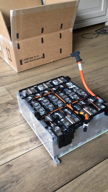
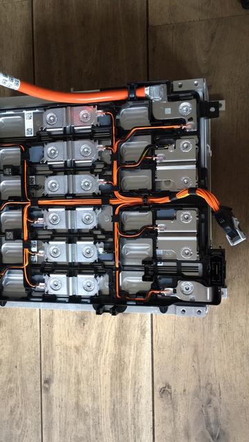
If you care about this data the Torqeedo motor can of course also be fed by a regelar external battery. Lead acid was immerdiately no option for me because of the weight. I then began to investagate which battery Torqeedo uses and found out that inside the Torqeedo Power 48-5000 housing a BMW i3 120Ah module is located.
So I bought this module this week and I m now up for the tast of making this unit ready for my motor.
Allright, let s first start with some basics that I learned. Please feel free to correct me where I m not thinking in the right direction.
1.
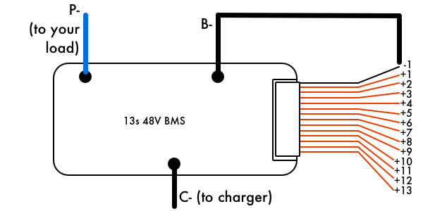
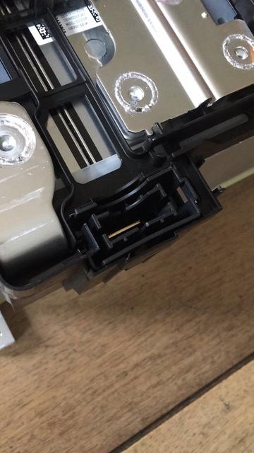
The most important thing is the BMS system. As you can see on the pictures there already is a nice wire harness running to all 12 cells (Samsung prismatic SDI cells). The cable has a 26pin connector on the end. My goal in to connect a BMS module directly on this connector.
2.
The BMS system itself:
I want a BMS system that can
- balance all 12 cells separately
- Also the BMS system has to take care of the charging process so I don t want my cells to overload the maximum capacity (4.19V)
- The BMS system need to check the cell voltage during sailing so it does not reach 2.79V
- Temperate will not be a problem so monitoring this is not really needed
3.
The charger:
Can I just take any common 48v charger with a maximum of around 50A (fast charging) and a minimum of around 10A (slow charging, approx one night)?
4.
Housing of the battery pack:
This will be for the last step and I think the leasy difficult part but that is for later.
5.
More about the BMS system:
- Do you guys have a recommendation for a cheap but good BMS system? Is eg. the Emus MINI bms a good choice?
- I know that the BMS system has to be connected to the cable harness that runs to all cells but how will the BMS monitor the cells while charging. What I mean is: I connect the charger to the charger to the MIN and PLUS pole directly correct? How does the BMS work then? Do I have to feed it separately with 12v?
- The same questions count for "while sailing": does the BMS need a separate 12v feed? Or does the BMS gets power from the pack itself?
6.
Connection:
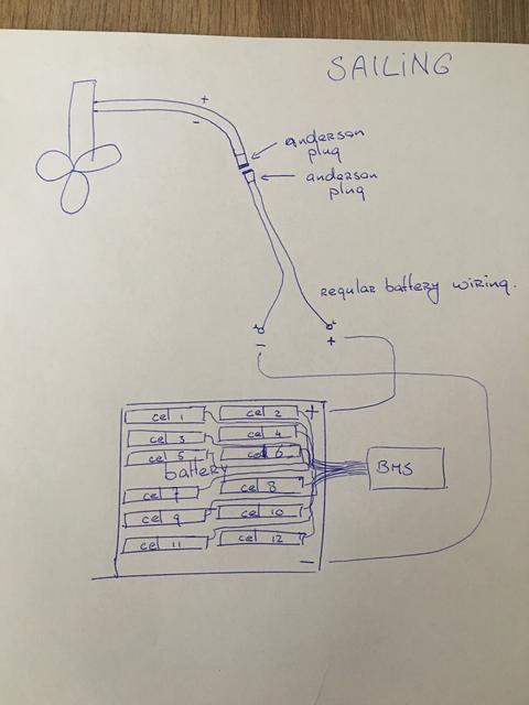
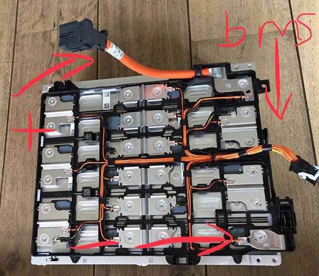
I will have to take care of the right connections. The PLUS and MIN pole will have to be cut at the end. I will then have to make Anderson plugs (or something like that) on the cable to run these to my motor (which also has Anderson plugs). The cable on the BMW module is thick aluminium. Will it be attach a (Anderson) plug on this?
Please note on the pictures below that there is no cable comming from the MIN pole on the package but I ordered this cable and will have it in the next few days.
One last thing: this is not a topic for letting me know that this is dangerous stuff and that I need to know what I doing and that this is not for people like me who don t know %*&# about these things. Of course I will not do anything if I cannot do it myself. I m really looking for substansive comment on my initial questions I ask in this topic.
Thanks for all input!
Gr.
Let me first say that I am by no means an expert in the world of batteries, voltages etc. at all. Despite this I m planning on building my own battery pack for my Torqeedo motor for my dinghy.
So, I own a Torqeedo Cruise 4 motor which consumes 4000watt at full throttle, has a nominal voltage of 48v so approx 83A.
Torqeedo sells its own battery for this motor, the Torqeedo Power 48-5000 pack (5kWh). This battery pack comes at a pretty high price, $ 5.000,00. For this money you get a battery pack with a very nicely integrated BMS in the battery which can communicate with the motor. This way you have all sort of information directly on the display on the motor like remaning sailing distance and time.
If you care about this data the Torqeedo motor can of course also be fed by a regelar external battery. Lead acid was immerdiately no option for me because of the weight. I then began to investagate which battery Torqeedo uses and found out that inside the Torqeedo Power 48-5000 housing a BMW i3 120Ah module is located.
So I bought this module this week and I m now up for the tast of making this unit ready for my motor.
Allright, let s first start with some basics that I learned. Please feel free to correct me where I m not thinking in the right direction.
1.
The most important thing is the BMS system. As you can see on the pictures there already is a nice wire harness running to all 12 cells (Samsung prismatic SDI cells). The cable has a 26pin connector on the end. My goal in to connect a BMS module directly on this connector.
2.
The BMS system itself:
I want a BMS system that can
- balance all 12 cells separately
- Also the BMS system has to take care of the charging process so I don t want my cells to overload the maximum capacity (4.19V)
- The BMS system need to check the cell voltage during sailing so it does not reach 2.79V
- Temperate will not be a problem so monitoring this is not really needed
3.
The charger:
Can I just take any common 48v charger with a maximum of around 50A (fast charging) and a minimum of around 10A (slow charging, approx one night)?
4.
Housing of the battery pack:
This will be for the last step and I think the leasy difficult part but that is for later.
5.
More about the BMS system:
- Do you guys have a recommendation for a cheap but good BMS system? Is eg. the Emus MINI bms a good choice?
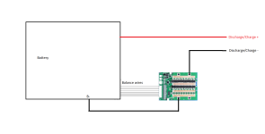
- I know that the BMS system has to be connected to the cable harness that runs to all cells but how will the BMS monitor the cells while charging. What I mean is: I connect the charger to the charger to the MIN and PLUS pole directly correct? How does the BMS work then? Do I have to feed it separately with 12v?
- The same questions count for "while sailing": does the BMS need a separate 12v feed? Or does the BMS gets power from the pack itself?
6.
Connection:
I will have to take care of the right connections. The PLUS and MIN pole will have to be cut at the end. I will then have to make Anderson plugs (or something like that) on the cable to run these to my motor (which also has Anderson plugs). The cable on the BMW module is thick aluminium. Will it be attach a (Anderson) plug on this?
Please note on the pictures below that there is no cable comming from the MIN pole on the package but I ordered this cable and will have it in the next few days.
One last thing: this is not a topic for letting me know that this is dangerous stuff and that I need to know what I doing and that this is not for people like me who don t know %*&# about these things. Of course I will not do anything if I cannot do it myself. I m really looking for substansive comment on my initial questions I ask in this topic.
Thanks for all input!
Gr.
") . First investigation
. First investigation