At long last: A SimpleBMS (up to 400v packs)

ntsh

1 µW
Joined
Oct 28, 2019
Messages
4
I couldn't find a super simple cheap BMS for my projects a year ago so I made one. Works pretty good, driving it in my car, software needs some fleshing out.

All the relevant info is here at this dumb hackaday page I made: https://hackaday.io/project/168126-simplebms
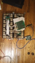
You might wonder why I used Ltc6804 chips? You can get super cheap ones from china, like $5 a chip if your lucky. All in all a 24s measurement card (with balancing and temp sensors) should cost under $50 if you make it yourself (now that's cheap).

This thing's basically supposed to be the opposite of FoxBMS and the like, a barebones ghetto BMS setup for projects.

i'd love to get some people using this, super happy to help people get up and running with a setup!
 
How would this work with say 6S modules used either independently, or as sub-packs, combined themselves into xSyP meta-packs?

Better URL: https://hackaday.io/project/168126-simplebms
 
FWIW, your URL is the same as his URL.


Quoted below is the entire text of the page that I can see, and as far as I can tell, the line on that page "nothingtoseeherenothingtoseehere" is accurate. There is more info in the first post of this thread than there is on that page. :/

Well, there is a single picture of some electronics that might be a BMS (also attached).

So...this thread could be seriously improved by the OP by posting the actual details and information about this "SimpleBMS".


Hack a Day

Projects
Lists
Contests
Stack
More

Sign up
Log In

SimpleBMS

At long last a cheap open source BMS
nothingtoseeherenothingtoseehere
Follow project
Like project
Join this project
Public Chat
0
comments
1
followers
0
likes

Description Details Files 0 Components 0 Logs 0 Instructions 0 Discussion 0

View Gallery
Public Chat
0
1
0
Team (1)

nothingtoseeherenothingtoseehere

Join this project's team

sr.ht

hardware
ongoing project
electric vehicles BMS kicad Battery management system

This project was created on 10/22/2019 and last updated 7 days ago.
Description
I wanted cheap simple bms for cool electric vehicles but none exist. So I embarked on the project of designing my very own ghetto bms setup.

What it does:
Composed of a controller board + measurement cards
Measurement cards can measure and passively balance up to 24 cells
Measurement cards can be daisy chained with a two wire connection, up to 108 cells
Support for two temperature sensors per measurement card
other super cool stuff you gotta find out man
Details

What it does:

Composed of a controller board + measurement cards

Measurement cards can measure and passively balance up to 24 cells

Measurement cards can be daisy chained with a two wire connection, up to 108 cells

Support for two temperature sensors per measurement card

other super cool stuff you gotta find out man

Enjoy this project?
Share
Discussions

Log In/Sign up to comment

Similar Projects
Complete controller of a toaster converted to a lab-grade PCB reflow oven.
Reflow2

J.R. StonerJ.R. Stoner
A small breakout board for the TMP75 temperature sensor
TMP75 Breakout Board

Dave's Dev LabDave's Dev Lab
This system uses DS18B20 temperature detection chip as the external detection equipment.
Temperature Detecting Heating Control System with

icstationicstation
Nordic nRF52840 dev board with sensors and a debugger.
Blip

Mahesh VenkitachalamMahesh Venkitachalam
Does this project spark your interest?

Become a member to follow this project and never miss any updates
Going up?

About Us Contact Hackaday.io Give Feedback Terms of Use Privacy Policy Hackaday API

© 2019 Hackaday
 

Attachments

  • 816661571723396076.jpg
    816661571723396076.jpg
    229.4 KB · Views: 1,194
Oh yeah sorry for the wonky descriptions, I've been really busy. I've been procrastinating on putting this project out there, and wanted to get it done one night.

You can see the setup I am running in my Honda Insight here: https://www.insightcentral.net/threads/another-lto-conversion-thread.121857/

I see no reason this shouldn't work for 6s submodules, as long as you have balance taps available.

Side note, the boards in my Insight are a little old. I have a new version with temperature sensors and 25 pin dsub connectors for the cells (13 pin jst sucks pretty bad). Planning to use them in my scratch built electric dirt bike project (I should make a thread for that). Not really sure what to add to the description, it's a simple bms based off of the LTC6804 chip. The kicad design files are linked on the hackaday page so you can check them out there.

If there are any specific questions I am happy to answer them!

Quick edit: Looks like hackaday doesn't make the sources link very clear, they can be found here: https://git.sr.ht/~simple_bms/
 
Is the colloquial language intended to prevent people from thinking you're supposed to be taken seriously?

If so, why?

Some detailed documentation whould be helpful, for those not into parsing code.

For example, are setpoints adjustable? Over what ranges?

Can you provide built examples, even if just prototypes?
 
haha well I'm writing an informal internet forum post about my project, so colloquial language seems the obvious choice for me... ?

Unless "EndlessSphere" is really a gathering place for the internet literati with strict writing formalities I am unaware of haha :D

Anyways...

Detailed documentation: This would be great, but a bit of a task to write haha. I'll hopefully try to write some soon. However, the design files I posted are not "code" per say, but files for the Kicad EDA. If you're able to download kicad, you should be able to pop em in and take a look at the boards. That reminds me I forgot to put the controller code online! good segue (nice job using a big word amirite? :D ) into the next part here...

So I'm not really sure what set points and ranges are, but here's my hopefully best answer: The ADCs on the cihp support voltages anywhere from 0-5 volts, slight caveat (hey another big one) is that if you're running some really low voltage cells (Titatane maybeL) you might not have a large enough voltage to power the stack.

Basically all of that would really come into play in the code though, but the code is pretty simple. I am using an arduino for the master controller at the bottom of the cells, but really any spi device would work if you put in the time to make it talk to the linear chipps. I've also not done a ton of work on the controller code, but hopefully that will change haha... Currently I have basic voltage based balancing and that's about it. Hoping to maybe count a couple of coulombs soon

Uhh built projects... So I've "built" the BMS that's running in my car? It's an 84s system, controlled with an arduino, LTO cells 2-2.7 volts ish. I drive with that everyday and it works pretty good! (well except for the cables but thats because of dumb jst cables I crimped i think)
 
I meant in the project descriptions on the project related websites.

IMO posts on the various forums are best for discussion, not documentation.

Details mentioned here, that are lacking in the project files, stuff scattered around people then have to search for & wade through kruft

Clear English helps get others involved, especially the world of very bright people with ESL.

Adjustability of setpoints: The user (not coder) can easily adjust e.g. the LVC, HVC, start balance voltages
 
hello simplebms friends, I haave added some documentation to the hackaday page. Please tell me if there are areas you would like to see expanded as i work on the documentation...

looking for cool friends to use bms (pm me...)
 
Back
Top