BMS not charging or discharging

KevMca

1 mW
Joined
Feb 8, 2020
Messages
10
I have a newly built 13s li-ion battery using the NESE battery modules. I have a cheap 13s BMS from banggood (https://m.banggood.com/13S-35A-48V-Li-ion-Battery-Protection-Board-BMS-PCB-with-Balance-For-E-bike-Scooter-p-1286039.html?rmmds=search#popupStatedetail). It's model is cf-60v20a-a.

The problem is that when I plug it in to charge it won't charge using my 13s charger and it also won't supply power to my ebike. Every group of cells is exactly 3.611V. I have used the charger before on an old battery pack. I have two connectors. The charge connector is connected to C- and the + of the battery and the power connector is connected to P- and the + of the battery.

What's weird is that the voltage across the charge connector is 44.5V and the voltage across the power connector is 43V. The battery pack is 47V so I would have presumed that it would be 47V on those connectors. Is this BMS dead, or am I connecting it incorrectly or something else entirely?
 
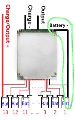
Is the battery negative wire (0V) also connected to the B- pad on the BMS? As per the large black wire in the diagram.

BATT-.jpg

Even though the BMS senses the battery negative through the balance wires, some BMSs don't function correctly unless you also have the battery negative connected to the main battery negative pad too. Just a quirk.

Failing that, I would probe each balance wire where they go in the BMS PCB, and check for the correct voltage at each point, just to be 100% sure each wire is connected to the correct cell.

e.g. Check for 4.2v, 8.4v, 12.6v, etc etc ensuring each balance connection increases by the appropriate cell voltage.

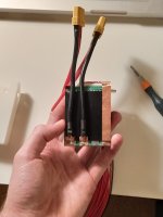
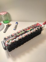
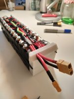
Can you upload some photos of your installation?
 
Thanks for the reply,

I have connected both the negative balance wire and terminal, I forgot to mention that previously. I have also checked each of the balance wires at the BMS PCB and they all seem to connected correctly as well.

IMG_20200205_230211.jpg
IMG_20200207_171737.jpg
IMG_20200207_171755.jpg

That's my setup there. It is essentially solderless, so I have bolted each of the connections together. Could this be a bottleneck perhaps? I have made sure to tighten everything so that good contact is being made.
 
:roll: I would put some extra sense wires on for a cellog for ez monitoring or a Bluetooth BMS would be cleaner. Write down each parallel group like.

1. 4.15
2. 3.95v
3. 3.85v


13. XXX volt this is state of charge. The important part.
Charge voltage
Battery voltage
Yes all please give us these info please.
Oh 13 x 4.2volt 54.6 volts
 
I don't know this specific BMS, so I'm a little confused by the main negative terminal connections. There appears to be 4 terminals, but only 3 labels (C P B).

Are you 100% sure you have it connected correctly? I'm not questioning your ability, just the ambiguity of the labelling on the BMS.

Neat job btw.
 
Thanks,

It's neat but it doesn't work XD I had a home built 13s battery before this, but I haven't used a BMS before, so I thought I could just be misunderstanding something.

B1:2.58
B2:3.60
B3:3.59
B4:3.60
B5:3.60
B6:3.60
B7:3.60
B8:3.60
B9:3.60
B10:3.60
B11:3.60
B12:3.60
B13:3.60

Those are the voltages across each corresponding pin at the BMS. As you can see, the first group is at 2.58V which is definitely an issue!!! What's weird is that I checked this a day ago and it seemed fine.

I'll keep ye posted!
 
Yes, the low cell voltage could definitely be causing the BMS to disconnect. But you'd still think it would allow charging.
 
no, because 2.58v is almost certainly below the "safe to recharge" lvc.

the references i usually see talked about here on es are around 2.7 to 2.8v for minimum cell voltages on 18650s, for instance. below this voltage the cell can sustain physical damage, depending on conditions, and may not be safe to recharge anymore, as such damage has the potential to lead to a fire.

so a bms can be designed to prevent a recharge if any cell is below this voltage, so you don't end up with a fire.
 
I think the low battery voltage is an issue because (according to banggood) the BMS cuts off at 2.55V and releases at 3.0V.

As you say, some discharge curves go down to 2V, so I'm hoping I can revive them. I'm going to trickle charge the low cells back to 3.6V using a variable power supply and see if they can be revived.

https://eu.nkon.nl/rechargeable/li-ion/18650-size/lg-inr18650-m29-2850mah-10a.html
^ These are the cells I am using their LG INR18650M29

It says they can discharge to 2.5V on their datasheet.
http://akkuplus.de/mediafiles/Datenblatt/LG/LG_INR18650M29.pdf

Here's hoping :wink:
 
Your own user-space LVCs should be controlling normal usage.

BMS is only there as a failsafe backup for when the main control hardware fails.
 
serious_sam said:
Yes, the low cell voltage could definitely be causing the BMS to disconnect. But you'd still think it would allow charging.
Two types of BMS

Dual port controls charge & discharge separately.

Single port not.

 
KevMca said:
I'm going to trickle charge the low cells back to 3.6V using a variable power supply and see if they can be revived.

Good plan.

If there's nothing specifically wrong with the cell, 2.58v in itself isn't necessarily bad for it (repeated discharge that low will obviously not be good for cycle life), but the issue will be what made that one cell go so much lower than the others.

john61ct said:
serious_sam said:
Yes, the low cell voltage could definitely be causing the BMS to disconnect. But you'd still think it would allow charging.
Two types of BMS

Dual port controls charge & discharge separately.

Single port not.

If the BMS turns the discharge mosfets off due to LVC, it should still leave the charge mosfets on to allow charging. The body diodes in the discharge mosfets still allow reverse current to flow through them back into the cells, even when they are off.

So I don't know what your point is.

If the BMS has also deactivated the charge mosfets due to the one cell being 2.58v, then that highlights the problem with the non-adjustable BMSs. You really don't know what the behaviour is in these cases, and you can't change the parameters if you want something different.
 
serious_sam said:
If the BMS turns the discharge mosfets off due to LVC, it should still leave the charge mosfets on to allow charging. The body diodes in the discharge mosfets still allow reverse current to flow through them back into the cells, even when they are off.

So I don't know what your point is.
My point is that many BMS are not designed to work that way.

MOSFETS may not even be controlling open/close, some use contactors to control higher currents.

BMS in the end are functionality only, implementation details are myriad,

so over-generalizations based on experience with a specific type of design & implementation, expectations of "should" vs reality, may lead others astray.

That is my point.

I completely agree that transparent operation, and user adjustability are desirable qualities, as would be good documentation and support, but many aren't willing to pay what that costs.


serious_sam said:
If the BMS turns the discharge mosfets off due to LVC, it should still leave the charge mosfets on to allow charging. The body diodes in the discharge mosfets still allow reverse current to flow through them back into the cells, even when they are off.

So I don't know what your point is.

If the BMS has also deactivated the charge mosfets due to the one cell being 2.58v, then that highlights the problem with the non-adjustable BMSs. You really don't know what the behaviour is in these cases, and you can't change the parameters if you want something different.

It's gotta to be the same LVC alarm circuit for both discharge and discharge. It would be a duplication to have two alarm circuits each with their own set points, esepcially for a 14 dollar BMS. It's going to shut off and stay off. Maybe KevMCA can balance that one group, or just swap in 4 spares.
 
docw009 said:
It's gotta to be the same LVC alarm circuit for both discharge and discharge. It would be a duplication to have two alarm circuits each with their own set points, esepcially for a 14 dollar BMS. It's going to shut off and stay off. Maybe KevMCA can balance that one group, or just swap in 4 spares.

You keep stating guesses as if they're facts.
 
john61ct said:
BMS in the end are functionality only, implementation details are myriad, so over-generalizations based on experience with a specific type of design & implementation, expectations of "should" vs reality, may lead others astray.

Which is why I said "should" and not "does". It's not a generalisation, it's the application of logic to how the operation "should" function (and does in some other BMSs).

Wow, I make one comment about how the LVC disabling charging is illogical (effectively bricking the pack if it was sealed), and everyone gets their panties in a knot.
 
Nothing twisted here, just clarifying.

Our democracy should be well protected by the Constitution

some may interpret as a prediction

rather than just wishful thinking.
 
john61ct said:
Nothing twisted here, just clarifying.

Our democracy should be well protected by the Constitution

some may interpret as a prediction

rather than just wishful thinking.

Yeah, well, opinions are like assholes. Everyone's got one.
 
Alright lads,

So I changed out those cells now and I now have a battery with the following voltages:

B1: 3.53V
B2: 7.1V
B3: 10.7V
B4: 14.3V
B5: 18.0V
B6: 21.6V
B7: 25.2V
B8: 28.8V
B9: 32.4V
B10: 36.0V
B11: 39.6V
B12: 43.2V
B13: 46.8V

There is still a 43V between P- and positive and 44.5V between C- and positive.
When I plug in my charger, it doesn't charge. And when I plug in my load it doesn't discharge.

I might just get a new BMS at this stage! Is there anyone ye would recommend?
 
KevMca said:
I might just get a new BMS at this stage! Is there anyone ye would recommend?

The "generic" Chinese bluetooth BMSs are good value.

You can adjust a lot of the parameters, calibrate the voltage for each series channel down to 1mV, and monitor the pack/cell voltages and temperatures with a smartphone.

They are more expensive than the one you have though.

https://endless-sphere.com/forums/viewtopic.php?f=14&t=88676

I bought a 20s 50 amp unit that I upgraded shunts and mosfets, and it runs 150 amps with almost no heat. I'm happy with it so far.

They aren't very fast achieving initial balance, so I'd recommend initially paralleling all your cells to get them all at the same voltage.
 
The problem I see is you have your + connected to the c- and p- . Bat- to bms B-, charger - to bms c- and load- to p- . Battery+ is only connected to the bms to provide power. Individual cell + to each sense wire. Like this:

https://ae01.alicdn.com/kf/HTB1kfwDcPJTMKJjSZFPq6zHUFXaP.jpg?size=187922&height=666&width=800&hash=d963c4aa981a317a70f2057ec3d81d02


Sent from my iPhone using Tapatalk
 
The connectivity shown in KevMCA's pictures make sense to me. Might be a problem with the copper strips screwed down to solder pads passing current. Could be oxidation on both surfaces. Did he pull the balance connector and measure the balance voltages at the connector, using pins?

What happens if he bypasses the BMS to see if the pack can run the ebike. Connect an XT connector across the battery and the B- terminal. See if bike runs. If it does, it also should charge across that plug, but for safety just check it briefly. That will test the integrity of the cell connections.

I think I've put in about a half dozen different BMS cards, bought about 10 of them, and the only ones I ever saw not work were made by JBD. They had ON/OFF circuits that didn't work.
 
The + side only connects to the load and the charger and the power in for the bms. Then the sense wires are connected to each cell +. If the load and charge + are the only connected to the b- and c- it will not work.


Sent from my iPhone using Tapatalk
 
Back
Top