Watt Meter With Open Hall Sensor?

rg12

100 kW
Joined
Jul 26, 2014
Messages
1,591
https://www.ebay.com/itm/Wireless-V...5&algv=default&_trksid=p2047675.c100008.m2219
I need something like this for DC that has the option to place a wire inside the hall like a clamp meter so I won't need to cut wires to get them through the hall sensor.

I need this for current testing on ebikes and the clamp meter will have to hang under the bike so I can't see the amps.
This unit lets me have a small wire going to the display mounted on the handlebar for easy testing.
 
rg12 said:
Is there a mV and resistance stuff with a hall current sensor like a shunt?
The auction description says "±200A/2.5±0.625V".

So it needs 5V to operate, and it outputs 2.5V +3.125mV/A.
 
serious_sam said:
rg12 said:
Is there a mV and resistance stuff with a hall current sensor like a shunt?
The auction description says "±200A/2.5±0.625V".

So it needs 5V to operate, and it outputs 2.5V +3.125mV/A.

Hmm, will that work?
The hall sensor that comes with the watt meter has 4 wires (seen in the photo) but I don't know how many wires the one in the other link has...
I sent a question about that for the hall sensor seller.
 
rg12 said:
https://www.ebay.com/itm/Wireless-V...5&algv=default&_trksid=p2047675.c100008.m2219

I need this for current testing on ebikes and the clamp meter will have to hang under the bike so I can't see the amps.

Those things are notoriously inaccurate and weird to program. I have one and it is accurate +/- 1-2A. Cannot sense low currents. Do not know how accurate it is at high currents. A Cycle Analyst and a shunt is much much more accurate. I know you want a " hall sensor shunt" and " easy to install"... but they are inaccurate unless you just want an" idea "as to the current up high. You can get inline shunts for the CA3..... but yeah cannot be placed without cutting line and I know that is what you dont want to know.

I do not know if a (0-5v) Hall sensor can be adapted to the CA current sensing system. You could probably adapt the "split" 0-5v Hall current sensor to the Chinese Watt meter display easily.


Yes they count Wh and Ah... but.... they need to be set up every time if you dont to a "discharge>charge cycle".... If you are just trying to count the Wh or Ah ...they stop reporting at a taper current setting ( termination under say... 2A.... ) and all that data is lost on an accurate charge. The machine itself operates reliably and the Hall sensor is a good piece of kit when it comes to design.. just no resolution down low.....

I have one, and just monitor charge on my bulk charger. It cannot know the difference tween 0.3A.. 0.6A.. and 1A... sits there and blinks between 0A-0.6A-0A on the last half an hour of my ( charger controlled ) taper current.

I got a ton of typical Honeywell Hall sensor current sensors. If you were local I would just send ya one to play with. All ya got to do is power them, and read the (0-5v) voltage on the signal wire to know the current (amount) traveling through the shunt.


If you are really cheap.. just disassemble your clamp meter... and make it a "remote sensing clamp meter" lol.
 
rg12 said:
Hmm, will that work?
The hall sensor that comes with the watt meter has 4 wires (seen in the photo) but I don't know how many wires the one in the other link has...
Not directly. The sensor with the original device you posted looks like it might be this one https://www.aliexpress.com/i/4000106225260.html which has an output of 2.5V±2V/100A, so it has a higher sensitivity than the last one you posted (2.5±0.625V/200A). You'd need to amplify the signal by 2/0.3125 = 6.4x

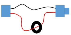
One option would be to make a short cable with male/female connectors and the current sensor fitted, then just fit that cable in-line with your battery connection. Then no need to cut the bike wiring.

Presentation1.jpg

What exactly is the purpose of the testing ? How accurate do you need it to be ?
 
serious_sam said:
rg12 said:
Hmm, will that work?
The hall sensor that comes with the watt meter has 4 wires (seen in the photo) but I don't know how many wires the one in the other link has...
Not directly. The sensor with the original device you posted looks like it might be this one https://www.aliexpress.com/i/4000106225260.html which has an output of 2.5V±2V/100A, so it has a higher sensitivity than the last one you posted (2.5±0.625V/200A). You'd need to amplify the signal by 2/0.3125 = 6.4x

One option would be to make a short cable with male/female connectors and the current sensor fitted, then just fit that cable in-line with your battery connection. Then no need to cut the bike wiring.

Presentation1.jpg

What exactly is the purpose of the testing ? How accurate do you need it to be ?

That is Chinese for me...
I read the descriptions for halls and it's something like 200A/4V +-15V...
Can you please help me find a 150A or 200A split core hall to fit the device I posted?
Many have the 4 wires (sometimes even 6 wires) but the voltage thing confuses me.
 
I think that if you're going to replace the current sensor, you should understand what you're doing, and do it for yourself. It's easy to understand. Don't fear it.

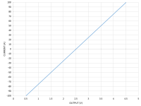
The sensor supplied with the display (probably, as per my assumption in previous post) has the following output (sensitivity): 2.5V±2V/100A, and operates from a 5v supply.

So:
- There are 4 wires.
- 2 wires are the 5V supply.
- 2 wires are the output.
- It operates between -100A and +100A.
- It outputs 2.5V when it senses 0A.
- It outputs 2.5V+2V=4.5V when it senses 100A.
- It outputs 2.5V-2V=0.5V when it senses -100A.
- The voltage output is proportional to the current it detects in-between those limits.
- So for example, at half the max current, it outputs half the max voltage => at 50A it outputs 2.5V+1V=3.5V.

graph.png
 
So how does that translate to a "50mV" shunt?

I have BMs that will accept 20A to 1000A, so long as that spec.

Larger capacity at much lower accuracy for lower currents.
 
john61ct said:
So how does that translate to a "50mV" shunt?

I have BMs that will accept 20A to 1000A, so long as that spec.

Larger capacity at much lower accuracy for lower currents.
A Current Shunt measures current, big, small, and everything in between.

A Current Shunt Resistor is a ( typical metal block with current passing through with two extra wires at each end, also down to the tiny resistances in pcb circuitry, known values.. ) device that puts a number (A) on a flow of current through a circuit based on known calibrations of a voltage drop (mV) through a calibrated part of the circuit, and some other voltage sensing circuitry to sense this ( calibrated ) voltage drop. This is the tried and true way of measuring the current ( v drop through calibrated chunk of metal) for a long time by now.. and typically use mV drop in the formula used to calculate the current.

A Hall effect Current Shunt is a ( what Rg is looking at, for, in a split config, so as not to cut his measured current carrying conductor and still measure) device that puts a number (A) on the current flowing through a circuit using current induced into a ring of magnetic material ( by passing through it ) ( steel) (ferrite) and measured with the output of a powered Hall Effect Sensor, which is a semiconductor device that registgers the strength and presence of a magnetic field in one direction or another.. typically read by an I/O circuit pull up or pull down on a processor. They are fast and reliable, more modern, and cheap. They dont get in the way of the current in the conductor, among other things. They are an isolated semiconductor device... used in many applications worldwide.

Two different things.

mV ( drop) = Shunt resister

0-5v (typical) = Hall Sensor output

Both measure it, and are used in design. I have seen BMS either, or, as the "main current input". The big hall sensor on the expensive and mid range EV BMS to the tiny little, appropriately sized resistors on the ebike BMS we all like.

RG might be able to" make" a Current Transformer. (CT) is a type of transformer that is used to reduce or multiply an alternating current (AC). It produces a current in its secondary which is proportional to the current in its primary.

A current transducer modifies the input on a primary conductor to a different type of signal on the secondary conductor.
https://www.digikey.com/en/article...-Umro50jnEgUk4vhJGusRVaQ2cMd-mIBoCyXcQAvD_BwE
 
serious_sam said:
I think that if you're going to replace the current sensor, you should understand what you're doing, and do it for yourself. It's easy to understand. Don't fear it.

The sensor supplied with the display (probably, as per my assumption in previous post) has the following output (sensitivity): 2.5V±2V/100A, and operates from a 5v supply.

So:
- There are 4 wires.
- 2 wires are the 5V supply.
- 2 wires are the output.
- It operates between -100A and +100A.
- It outputs 2.5V when it senses 0A.
- It outputs 2.5V+2V=4.5V when it senses 100A.
- It outputs 2.5V-2V=0.5V when it senses -100A.
- The voltage output is proportional to the current it detects in-between those limits.
- So for example, at half the max current, it outputs half the max voltage => at 50A it outputs 2.5V+1V=3.5V.

graph.png

Thanks for the awesome explanation!

I can't find a 2.5±2.0V split core on eBay and AliExpress search is much less accurate and I can't find anything there too.
I just noticed that in the device's listing one of the photos shows the back of the original hall that has two trim pots.
What are they trimming exactly?
What would you do if you had to make this work without building circuits/adding components to have a 150A capable split core hall to fit this device?
Also, something weird there in the specs...it says:
"Voltage Range 0.01~120V (external power), 6.00~80.0V (internal power)"
Does it mean that if the battery to be measured is powering the device that it will accept only up to 80V?
 
rg12 said:
What are they trimming exactly?
Probably calibration of the output. They are likely factory set with some glue added on top to lock the setting.

rg12 said:
What would you do if you had to make this work without building circuits/adding components to have a 150A capable split core hall to fit this device?
By definition, if you don't want to do any circuit building, then the only option is to find a direct swap out replacement for the current sensor.

But you haven't given much details on exactly what/why you're doing, and why you can use the jumper cable I suggested?
 
serious_sam said:
rg12 said:
What are they trimming exactly?
Probably calibration of the output. They are likely factory set with some glue added on top to lock the setting.

rg12 said:
What would you do if you had to make this work without building circuits/adding components to have a 150A capable split core hall to fit this device?
By definition, if you don't want to do any circuit building, then the only option is to find a direct swap out replacement for the current sensor.

But you haven't given much details on exactly what/why you're doing, and why you can use the jumper cable I suggested?

I need this for testing the current draw on ebikes that don't have a display that shows current.
I don't wanna go on cutting the main wire and place a shunt nor use the jumper option as each bike has a different type of connector or no connector at all and all is just soldered so the split core option is perfect for that.
Plus, I don't need low current resolution accuracy, it's all between 20 to 150 maybe 200 amps.
 
So if it's just real-time current monitoring, and not data logging, then go with dipstick's idea, and modify a clamp meter. Perfect.

DogDipstick said:
If you are really cheap.. just disassemble your clamp meter... and make it a "remote sensing clamp meter" lol.
 
serious_sam said:
So if it's just real-time current monitoring, and not data logging, then go with dipstick's idea, and modify a clamp meter. Perfect.

DogDipstick said:
If you are really cheap.. just disassemble your clamp meter... and make it a "remote sensing clamp meter" lol.

It's a bit hacked up and the clamp is huge...
I just need the right hall to fit the device and it's perfect.
 
I thought a device designed to work with a shunt, needs a shunt.

If you want to use a hall sensor, then you need a wattmeter designed to work with a hall sensor.

IMO
 
john61ct said:
I thought a device designed to work with a shunt, needs a shunt.
If you want to use a hall sensor, then you need a wattmeter designed to work with a hall sensor.
IMO
There is no shunt.

Please re-read the title, the OP, and the original eBay link. No shunt mentioned.
 
john61ct said:
So how does that translate to a "50mV" shunt?
I have BMs that will accept 20A to 1000A, so long as that spec.
Larger capacity at much lower accuracy for lower currents.
50mV shunt means it outputs 50mV at full scale (whatever the current that it's rated for. e.g. 50mV@50A). So I assume that your BMS has some programmability that will allow you to tell it what that current rating of the shunt you use is.
 
Sorry not BMS but BM

Battery Monitors, as in coulomb-counting SoC% meters costing hundreds, used on mobile House banks, say 400-1400Ah in size.

And yes, and thanks
 
Back
Top