18650 battery pack design for a powerbank

CyPF

100 µW
Joined
Jul 12, 2017
Messages
9
Hello,
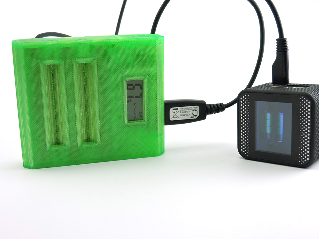
I would like to make an external battery (powerbank) in wood with 18650 PANASONIC NCR18650B 3400 mAh batteries. The goal is to have a high-performance and reliable battery over time. I would like to use 6 batteries to build this Power Bank, however I have several questions about its realization.

Specification: I need the battery pack to deliver a voltage of 5V under 2-5A (I'll probably need a buck converter to raise or lower the voltage).

My questions:

What is the best configuration in order to have optimal performance for autonomy, 1S6P, 2S3P?

What is the more efficient method, step-up or step-down the voltage?

Which reliable BMS do you recommend me for this project?

Thank you in advance for your future answers and wish you a good day!
 
2S3P is more efficient, as buck is usually more efficient than boost circuitry.

But for straight simplicity 1S6P is better, no need for a BMS system and the efficiency is already good enough with modern boost converters, going from 3~4.2v to 5V is pretty efficient nowdays, there are already pretty good solutions out there you would just need to populate with cells.

With 1S6P you can even mix different cells in a pinch without issues.
 
I have made one using my compression method and cheap powerbank boards. Can be made for 2 to 8 cells

jPp7ZMA.jpg
 
Schlafmutze said:
2S3P is more efficient, as buck is usually more efficient than boost circuitry.

But for straight simplicity 1S6P is better, no need for a BMS system and the efficiency is already good enough with modern boost converters, going from 3~4.2v to 5V is pretty efficient nowdays, there are already pretty good solutions out there you would just need to populate with cells.

With 1S6P you can even mix different cells in a pinch without issues.

Hello,
Thanks for your reply.
Alright,do you have an recommandation for 1S6P BMS, most of them have an over-discharge cutting arround 2.5v it's not good for the 18650, i'm looking for 2.9v over-discharge cutting to optimize as maximum battery durability.
I have another question, for the configuration 1S6P, can the batteries become unbalanced over time?

agniusm said:
I have made one using my compression method and cheap powerbank boards. Can be made for 2 to 8 cells

jPp7ZMA.jpg
Hello,
Thanks for your reply.
Wow it's an nice project ! Which model of 18650 did you put inside ?
 
Batteries becoming unbalanced over time with a 1P config isn't possible as all of them are connected in parallel, so in practice all of the cells work like one large cell.

You don't need a BMS for 1P configs, and I'm pretty sure that low voltage cut off on most of those ready made circuit boards used in 5V supplies have a cut off around 3v, which is alright.
Even with 2.5v you're unlikely to see 200+ cycle usage on a powerbank anyway.
 
Schlafmutze said:
Batteries becoming unbalanced over time with a 1P config isn't possible as all of them are connected in parallel, so in practice all of the cells work like one large cell.

You don't need a BMS for 1P configs, and I'm pretty sure that low voltage cut off on most of those ready made circuit boards used in 5V supplies have a cut off around 3v, which is alright.
Even with 2.5v you're unlikely to see 200+ cycle usage on a powerbank anyway.
I understand, I have question about charging the battery pack. Can i charge it with an 5V Wall Charger combined with a step down to 4.2V ? The BMS will stop the charge ? Like this one :https://www.aliexpress.com/item/327...earchweb0_0,searchweb201602_,searchweb201603_
 
You could, but if you're going to buy something anyway, why not buy a single-cell charger that already outputs the voltage you want, at the current you want?

Or use an adustable-voltage adjustable-current CC/CV power supply (often called an LED PSU or Lab PSU), that can be set to the voltage you want.

I think Meanwell makes some that go down to the voltage you want; they also make some that are just made for 4.2v. You just have to make sure they have CC type current limiting rather than "hiccup" type limiting, so that they can act as chargers.
 
You are thinking to hard for a simple solution. There are many powerbank pcb's and they cost nothing. They have built in charging and conversion, output 2.4A and could be charged with regular smartphone charger, PC, TV, or anything else that has usb.
There are also QC powerbank pcb for a little over 10$ that output more current and or voltage.
 
amberwolf said:
You could, but if you're going to buy something anyway, why not buy a single-cell charger that already outputs the voltage you want, at the current you want?

Or use an adustable-voltage adjustable-current CC/CV power supply (often called an LED PSU or Lab PSU), that can be set to the voltage you want.

I think Meanwell makes some that go down to the voltage you want; they also make some that are just made for 4.2v. You just have to make sure they have CC type current limiting rather than "hiccup" type limiting, so that they can act as chargers.
Because i' would like to charge the battery pack with a simple phone wall charger .The final product that will have the battery pack must be easy to use and avoid to buy specific CC CV external lithium wall charger to charge it. Hope to be clear as possible :D

If i use LED PSU, how to automatically cut-off at 4.2v when the battery pack is charged ? What do you think aboutthis charging module? https://www.aliexpress.com/item/400...earchweb0_0,searchweb201602_,searchweb201603_
 
agniusm said:
You are thinking to hard for a simple solution. There are many powerbank pcb's and they cost nothing. They have built in charging and conversion, output 2.4A and could be charged with regular smartphone charger, PC, TV, or anything else that has usb.
There are also QC powerbank pcb for a little over 10$ that output more current and or voltage.
I know, but really want to understand how all this things works and not buy ready board, i do this to have more freedom in my future projects.
 
CyPF said:
agniusm said:
You are thinking to hard for a simple solution. There are many powerbank pcb's and they cost nothing. They have built in charging and conversion, output 2.4A and could be charged with regular smartphone charger, PC, TV, or anything else that has usb.
There are also QC powerbank pcb for a little over 10$ that output more current and or voltage.
I know, but really want to understand how all this things works and not buy ready board, i do this to have more freedom in my future projects.
You will buy ready boards anyway. the difference is that those powerbank pcb modules have everything built in and you will end up soldering bunch of components leaving you with a messy wiring, more money spent and bigger solution. just my 2ct
 
CyPF said:
Because i' would like to charge the battery pack with a simple phone wall charger .The final product that will have the battery pack must be easy to use and avoid to buy specific CC CV external lithium wall charger to charge it. Hope to be clear as possible :D
Makes sense.

If i use LED PSU, how to automatically cut-off at 4.2v when the battery pack is charged ?
You said you were using a BMS, right? That should have protections against overcharge and overdischarge (otherwise it's not much of a BMS)

But the real protection is that you set the PSU to only 4.2v, so it cannot exceed the full charge voltage of the cells.
 
amberwolf said:
Or use an adustable-voltage adjustable-current CC/CV power supply (often called an LED PSU or Lab PSU), that can be set to the voltage you want.
Hi amberwolf, I am using the way you mentioned to charge some of my batteries, and it works for me. Recently, I came across a power supply. It has a charging function/mode which uses a different output connection (green colour one but not the red one). I do not understand why they have to do that. I have asked them but I could not understand their reply. Could you please kindly explain the reason for me? The links of it are as follows:
https://www.aliexpress.com/item/4000282551930.html?spm=a2g0o.cart.0.0.4e033c00K400uG&mp=1
https://www.youtube.com/watch?v=fn6ROhGrLtI (My comments are the 21st from the top, my youtube account name is TM HO)
 
I don't understand what you mean by
tmho said:
It has a charging function/mode which uses a different output connection (green colour one but not the red one).
I can't access aliexpress today; everything just comes up blank but with colored shapes where blocks of data should be. (this happens with some frequency, doesn't matter what browser I use, so I suspect it is something to do with IP routing or blocking between me and them--same thing happens with various imagehosting sites like imgur).
 
amberwolf said:
I don't understand what you mean by
tmho said:
It has a charging function/mode which uses a different output connection (green colour one but not the red one).
I can't access aliexpress today; everything just comes up blank but with colored shapes where blocks of data should be. (this happens with some frequency, doesn't matter what browser I use, so I suspect it is something to do with IP routing or blocking between me and them--same thing happens with various imagehosting sites like imgur).
If both the Aliexpress and Youtube links do not work for you, may be you can search it on the internet. The power supply I am talking about is RIDEN RD6006.
 
amberwolf said:
CyPF said:
Because i' would like to charge the battery pack with a simple phone wall charger .The final product that will have the battery pack must be easy to use and avoid to buy specific CC CV external lithium wall charger to charge it. Hope to be clear as possible :D
Makes sense.

If i use LED PSU, how to automatically cut-off at 4.2v when the battery pack is charged ?
You said you were using a BMS, right? That should have protections against overcharge and overdischarge (otherwise it's not much of a BMS)

But the real protection is that you set the PSU to only 4.2v, so it cannot exceed the full charge voltage of the cells.
The battery will have Protection BMS alright. I understand, but just Imagine you forgot to unplug the battery pack fully charged, during 2hours the battery pack will receive 4.2V in continious That would risk degrading it, right?
I think is important to cut-off the currrent when the battery is fully charged, do you have an another solution, like i said the imput must be simple and easy to carry as phone charger. Psu is too big haha

And What do you think about this charging module?
https://fr.aliexpress.com/item/4000130857356.html?spm=a2g0o.productlist.0.0.59584247fcNYba&algo_pvid=5cdb9060-257a-441a-a16b-64732b6151b7&algo_expid=5cdb9060-257a-441a-a16b-64732b6151b7-0&btsid=0b0a3f8115927834481033455e5193&ws_ab_test=searchweb0_0,searchweb201602_,searchweb201603_
 
tmho said:
Hi amberwolf, I am using the way you mentioned to charge some of my batteries, and it works for me. Recently, I came across a power supply. It has a charging function/mode which uses a different output connection (green colour one but not the red one). I do not understand why they have to do that. I have asked them but I could not understand their reply.

This may a little late but ...
You are correct in that the documentation is weak at best.

The GREEN battery terminal of the Riden RD6006 power supply is routed through relay that shuts down the output when the charging current drops below 0.10 amps (10mA). It is also supposed to be tied to the external temperature sensor to monitor the temperature of the battery while charging. Note also you should not use this terminal to charge a battery with a BMS (per Riden's documentation).
 
LewTwo said:
tmho said:
Hi amberwolf, I am using the way you mentioned to charge some of my batteries, and it works for me. Recently, I came across a power supply. It has a charging function/mode which uses a different output connection (green colour one but not the red one). I do not understand why they have to do that. I have asked them but I could not understand their reply.

This may a little late but ...
You are correct in that the documentation is weak at best.

The GREEN battery terminal of the Riden RD6006 power supply is routed through relay that shuts down the output when the charging current drops below 0.10 amps (10mA). It is also supposed to be tied to the external temperature sensor to monitor the temperature of the battery while charging. Note also you should not use this terminal to charge a battery with a BMS (per Riden's documentation).
Its never too late. Thank you! Now I understand.
 
Just found out one other little fact that they forgot to mention ...
the power supply goes into "Constant Voltage" mode (vs Constant Current).
This is the really important bit .... which begs the question why they left that detail out.
RD6006 CV Mode.JPG
 
LewTwo said:
Just found out one other little fact that they forgot to mention ...
the power supply goes into "Constant Voltage" mode (vs Constant Current).
This is the really important bit .... which begs the question why they left that detail out.
RD6006 CV Mode.JPG

When I first saw this power supply, I wondered if something like it could perform the same function as a 'Cycle Satiator'.

Then I noticed this comment, and I was curious to know how this would influence using any of the Riden regulator units as a charger? I'm guessing that you'd need a power supply that can use a CC/CV charging method?

Is CC/CV the sort of charging method a Satiator uses for example?

I was also curious as to why Riden mentions you cannot use that Power Supply regulator on batteries that have a BMS?
 
tsellers said:
Then I noticed this comment, and I was curious to know how this would influence using any of the Riden regulator units as a charger? I'm guessing that you'd need a power supply that can use a CC/CV charging method?
If you are speaking of the internal power supply then it is just a standard off the shelf, switching, variable power supply running at about 62.5 volts DC. The "Riden regulator" controls what is actually on the output connectors.

tsellers said:
When I first saw this power supply, I wondered if something like it could perform the same function as a 'Cycle Satiator'.
What 'function' would that be?
If you only want a 90% charge level then simply set the max voltage to 90%.
If you want to 'cycle' or 'discharge' the battery then you need an electronic load as well.

tsellers said:
I was also curious as to why Riden mentions you cannot use that Power Supply regulator on batteries that have a BMS?
I am curious as well.
On the other hand I am generally using this connected directly to the cells.

What it comes down to is that this is Chinese Product.
English documentation should never be expected to be totally accurate or complete.
 
LewTwo said:
tsellers said:
I'm guessing that you'd need a power supply that can use a CC/CV charging method?
The "Riden regulator" controls what is actually on the output connectors.
Thanks for the replies. I was wondering how important it is to use CC/CV charging as it seems the Riden regulator does not provide that at the output connectors.

tsellers said:
When I first saw this power supply, I wondered if something like it could perform the same function as a 'Cycle Satiator'.
What 'function' would that be?

- The same functions that the Satiator provides that regular chargers do not. EG: ability to set charge voltage is apparent, not sure about what else.

tsellers said:
I was also curious as to why Riden mentions you cannot use that Power Supply regulator on batteries that have a BMS?

I am curious as well.
On the other hand I am generally using this connected directly to the cells.

What it comes down to is that this is Chinese Product.
English documentation should never be expected to be totally accurate or complete.

According to a post on Reddit https://www.reddit.com/r/batteries/comments/8z8x84/2_3_and_4s_bms_modules_with_constant_current/, most BMS's require both CC and CV to be provided by the power supply. If the Riden does not provide CC, then I'd guess that is why it is not suitable.
 
tsellers said:
... most BMS's require both CC and CV to be provided by the power supply. If the Riden does not provide CC, then I'd guess that is why it is not suitable.
It does have both CV and CC modes.
If you are using the normal outputs then CC or CV depends on the output setting for the power supply.
It can only vary one of the two.
Once it hits the max of either Voltage or Current then it has to vary the other.
 
LewTwo said:
tsellers said:
... most BMS's require both CC and CV to be provided by the power supply. If the Riden does not provide CC, then I'd guess that is why it is not suitable.
It does have both CV and CC modes.
If you are using the normal outputs then CC or CV depends on the output setting for the power supply.
It can only vary one of the two.
Once it hits the max of either Voltage or Current then it has to vary the other.

Thanks, that's good info to know, especially as it sounds like you were mostly required to figure that out on your own using some trial and error. I've been considering their 18A unit since I started to consider getting a new power supply ayway, and then noticed it had that green battery charging port. The charger part of it would just be icing on the cake. I'm guessing then that if you do use it as a charger for Li-Ion cells, you need to be prepared to keep and eye on things and make adjustments as required during the charging cycle and at the end of it. I get the impression that that is what you're doing.
 
tsellers said:
[The charger part of it would just be icing on the cake. I'm guessing then that if you do use it as a charger for Li-Ion cells, you need to be prepared to keep and eye on things and make adjustments as required during the charging cycle and at the end of it. I get the impression that that is what you're doing.
NOPE.
I use the battery terminals. I set the max voltage I want and the max current I want to charge at. Connect up the cells (usually LiFePO4 for the record) and turn on the output. The current is usually the limiting factor so it starts in Constant Current mode. Eventually it switches to Constant Voltage mode and starts decreasing the current. It eventually shuts down when the charging current drops below 0.10 amps (10mA). I come back some hours later and record the Amp-Hours. Disconnect the battery and check the voltage with a DMM. The fully charged voltage is always a bit less than the maximum charging voltage. That is because the charge level drops a bit as the battery "rests".

By the way ... note the "CV" in the lower left corner of the display in the picture above. That indicates it was in "Constant Voltage" mode when the picture was taken.

The one thing I do not like about this PS is that it does not use a set of kelvin cables (one pair for power and a separate pair for reading the voltage at the battery). One can also not calibrate the PS for the cables (i.e. account for the voltage drop due to the resistance in the length of the cables). To get those features, I would likely have to spend a lot more money and I am a cheap ######.
 
Back
Top