
A previous topic I had covering my build went walkies so this is a new topic to check my thinking during my build. I have already had some super useful discussion in the aforementioned topic as well as doing plenty of reading on cell life and life cycling by the members here doing that testing.
I have settled on the battery I am using - The Samsung 50E, which I will be using at 70-80% of capacity to extend cycle life.
The pack is part of a swappable battery system powering a portable computer station, not a bike.
Wherever possible I will be looking to implement safety features in the design of the battery. The chances of failure are low, but the outcome of failure can be extremely damaging.
I am fusing each cell to internal bus bars, the layout I have in mind is shown here:
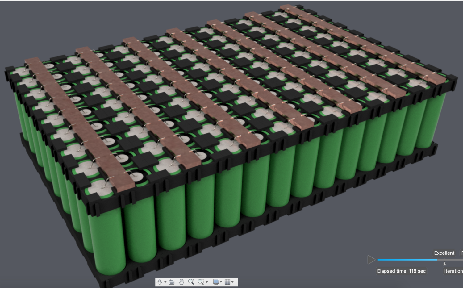
Each series cell is capable of 88A continuous, but the max load the system I am making would put on the cells is about 51A, and usually significantly lower than this. I would like to build in overheads however so I was think to spec the busbars to carry the full 88A.
I just wanted to check however that I was correct to think that each busbar between each series group needed to be able to carry the full 88A?
Assuming they do, I then used the following table:
https://www.powerstream.com/Wire_Size.htm
To get a cross sectional area required. So for a 10mm width and 1mm thick bar the "amps for chassis wiring" would be a bit under 89A.
So would a 10x1mm busbar with each cell individually fused be correct for this?
I have settled on the battery I am using - The Samsung 50E, which I will be using at 70-80% of capacity to extend cycle life.
The pack is part of a swappable battery system powering a portable computer station, not a bike.
Wherever possible I will be looking to implement safety features in the design of the battery. The chances of failure are low, but the outcome of failure can be extremely damaging.
I am fusing each cell to internal bus bars, the layout I have in mind is shown here:
Each series cell is capable of 88A continuous, but the max load the system I am making would put on the cells is about 51A, and usually significantly lower than this. I would like to build in overheads however so I was think to spec the busbars to carry the full 88A.
I just wanted to check however that I was correct to think that each busbar between each series group needed to be able to carry the full 88A?
Assuming they do, I then used the following table:
https://www.powerstream.com/Wire_Size.htm
To get a cross sectional area required. So for a 10mm width and 1mm thick bar the "amps for chassis wiring" would be a bit under 89A.
So would a 10x1mm busbar with each cell individually fused be correct for this?
") probably only an amp goes sideways but copper seems like a good heat sink for when a fuse wire blows, anyone look at using aluminum?
probably only an amp goes sideways but copper seems like a good heat sink for when a fuse wire blows, anyone look at using aluminum?