Battery Design advice sought

Joined
Oct 22, 2020
Messages
22
Hi All,

I have followed this site for a long time and learned so much so first thank you to everyone who has contributed their time and knowledge, it really is well appreciated.

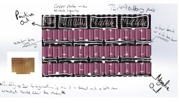
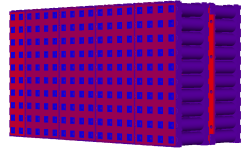
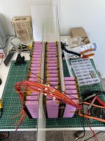
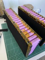
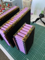
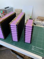
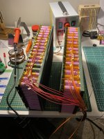
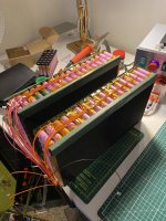
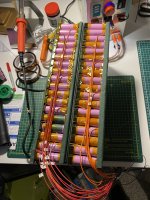
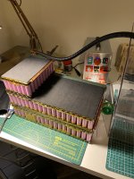
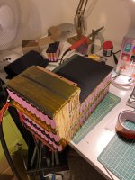
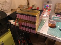
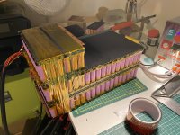
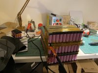
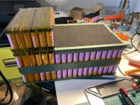
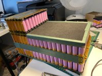
I have designed a pack for a 72v 3kw mid drive motor and want to get some good range (really good) out of it. With that in mind I am going for a 21s24p design, the current design shows 18p but I will be adding another 2 p lines. I realise this is slightly over voltage but my set up can handle that.

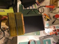
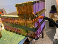
I have attached an image that I have drawn to illustrate how I intend to build the pack and would really appreciate any feedback on best practice and indeed better ways of doing it if that may be the case. I have left some annotations on there that may not be of interest so please disregard.

I guess I am just looking for some experienced eyes to look at this and either say yep good to go or STOP and rethink!

Obviously I will be insulating each layer and using kapton tape etc.

Thanks so much for looking and I look forward to your replies.

Sanch
 

Attachments

  • Inked72v Battery Pack_LI (2).jpg
    Inked72v Battery Pack_LI (2).jpg
    190.1 KB · Views: 1,592
Hi Goatman,

Thanks for the response.

The connections to the cells will be spot welded, hence the nickel inserts. the plates will be in an effective 2s10p and 4s10p configuration. I have described it that way for ease of understanding but in reality it will be the width of just under 2 cells inc holders and length of just under 10 cells inc holders with the nickel inserts added in the right places to be spot welded. The copper plate will be 0.7mm thick. the nickel inserts are 0.2mm thickness.

The cells themselves will be 35E cells, making the pack 84ah although I have changed the design a little since to remove a few cells making it 70ah total. The load on the pack will at most be 150ah which I calculate shouldn't put too much strain in the cells. Particularly as the general load will be around 50-70ah.

I understand that I am taking a sledgehammer to this in terms of cost. This is by design, I am not looking to massively reduce cost and do not want to use nickel strips.
 
150ah would be 2C/7amps

21s, 63volts x 150amps= 9kw motor

are you going to use cell holders to keep an air gap around the cells and then insulate it to maintain a balanced pack temperature?
 
Yes there is a 2mm airgap between each cell. It's a little difficult to see on the picture. Exactly right on the insulation.
 
Looks like a nice, well thought out layout. I think the area you need to focus on is the row to row connections. Everything else seems pretty standard. You've written "bend or side bus bar". I don't really like the bend - you'll have to do the welds first then bend it and it seems like it would stress the cells and welds while you're doing the bend. The "side bus bar" could work, but what exactly are you thinking there?
 
Thanks for your well considered response thepronghorn. I was thinking of insulating the two layers with some 2mil fish paper backed board and adding a 2mil copper bar to some extruded sides that can be bolted together. I will add an image to demonstrate this shortly.

Having thought further, I also don't like the idea of bending, it was a practice I saw a while ago and seemed to work well for him but I cringed at the time and probably for good reason! Assume bending is out of the equation! :D
 
Please see further pictures. I have not added any annotations at this stage but let me know if you feel they would be useful.

angled view normal.PNG
 

Attachments

  • Assembly View Side Bus.PNG
    Assembly View Side Bus.PNG
    14.1 KB · Views: 1,440
  • Assembly View Side.PNG
    Assembly View Side.PNG
    33.4 KB · Views: 1,440
  • Assembly View Side-top.PNG
    Assembly View Side-top.PNG
    31.1 KB · Views: 1,440
  • Assembly View Top-side.PNG
    Assembly View Top-side.PNG
    28.8 KB · Views: 1,440
  • Side view normal.PNG
    Side view normal.PNG
    30.8 KB · Views: 1,440
Between those stacks I'd be looking at a minimum of 4mm insulation thickness better 5-6mm. Must be fail safe. Must be resistant to pounding and vibration. 3mm plastic board, with softer lining each side like silicon sheet would be good. Fish paper alone is not adequate. Avoid at all cost any sensing wires traversing this area, but if a wire is to cross this area, make a channel for it and ensure the insulation is perfect.
Also, ensure the stacks are held tightly together in such a way they don't move independently on bumps, otherwise the movement between stacks will fatigue the copper connections and they could fail. You could add some length to that connection for some flex absorption. Can be bent up at right angle to keep profile low, but I've seen soft 0.2mm copper foil fatigue at junctions like this (and nickel). You want it to last millions of cycles of vibration, so ensure its packaged really well.
 
Thats great advice Kdog. I had considered bending the busbar upwards but wasn't sure if that would impact the flow of electricity.

There has been a slight further redesign in that we are now using 1mm copper plates with the 2mm connecting flat bar which gives 4mm total on the busbar connections.

I am going to put some more thought into the layer insulation so thanks very much for that advice.
 
Can you describe what you mean by nickel inserts? Are you planning to use the "sandwich" technique? The copper is pretty thick, have you made successful test welds yet?

Sent from my SM-T380 using Tapatalk

 
Hi Frank,

Apologies for the delay in responding, i've been finding it difficult to get onto the endless sphere website.

The nickel inserts are spot welded onto the copper using an overhang and then spot welded onto the individual cells. The method is effective and allows for very high amps without generating very much heat.
 
(To confirm my understanding) Does this mean that current flows for a very short distance from the cell through the nickel and onto the copper "bus bar"? i.e. There's nickel in the flow path but it's so short a distance that there's not much resistance.

Thanks!
 
Hi Frank,

Yes effectively correct. The nickel is only ever having to pass a single (individual) cell's energy through it, and even then for an extremely short distance. The copper is the conduit for the larger amps. The pictures above should give an idea for the flow.
 
Hi All,

For anyone who is interested. I have attached pictures of the pack. Throughout the build and completed. Hope it helps others. :bigthumb:
 

Attachments

  • IMG_5906.JPEG
    IMG_5906.JPEG
    379.2 KB · Views: 985
  • IMG_5925.JPEG
    IMG_5925.JPEG
    497.5 KB · Views: 985
  • IMG_5928.JPEG
    IMG_5928.JPEG
    288.8 KB · Views: 985
  • IMG_5930.JPEG
    IMG_5930.JPEG
    491 KB · Views: 985
  • IMG_5931.JPEG
    IMG_5931.JPEG
    568.5 KB · Views: 985
  • IMG_5932.JPEG
    IMG_5932.JPEG
    281.1 KB · Views: 985
  • IMG_5933.JPEG
    IMG_5933.JPEG
    278.7 KB · Views: 985
  • IMG_5935.JPEG
    IMG_5935.JPEG
    221.3 KB · Views: 985
  • IMG_5936.JPEG
    IMG_5936.JPEG
    253.7 KB · Views: 985
  • IMG_5937.JPEG
    IMG_5937.JPEG
    254.2 KB · Views: 985
  • IMG_5938.JPEG
    IMG_5938.JPEG
    252.9 KB · Views: 985
  • IMG_5939.JPEG
    IMG_5939.JPEG
    271.1 KB · Views: 985
  • IMG_5940.JPEG
    IMG_5940.JPEG
    300.5 KB · Views: 985
  • IMG_5941.JPEG
    IMG_5941.JPEG
    268.2 KB · Views: 985
  • IMG_5942.JPEG
    IMG_5942.JPEG
    237.5 KB · Views: 985
  • IMG_5943.JPEG
    IMG_5943.JPEG
    418.3 KB · Views: 985
  • IMG_5944.JPEG
    IMG_5944.JPEG
    444.6 KB · Views: 985
  • IMG_5945.JPEG
    IMG_5945.JPEG
    433.8 KB · Views: 985
  • IMG_5946.JPEG
    IMG_5946.JPEG
    382.5 KB · Views: 985
  • IMG_5948.JPEG
    IMG_5948.JPEG
    482.5 KB · Views: 985
  • IMG_5951.JPEG
    IMG_5951.JPEG
    466 KB · Views: 985
  • IMG_5952.JPEG
    IMG_5952.JPEG
    516.6 KB · Views: 985
Hi Sam,

I designed them and had them made. They are pressed and laser welded to the copper. It makes large pack making an absolute breeze, but wasn't cheap!
 
I sort of had that in mind when designing it. Not necessarily mass produce it, but have something of that quality. I've enjoyed the journey though and will be making more in the coming months!

I've learned a lot from this forum and would like to give back so please any questions I will do my best to answer.
 
Back
Top