How to handle series connection in a moderately large 18650 battery build?

David01

100 µW
Joined
Jan 18, 2021
Messages
9
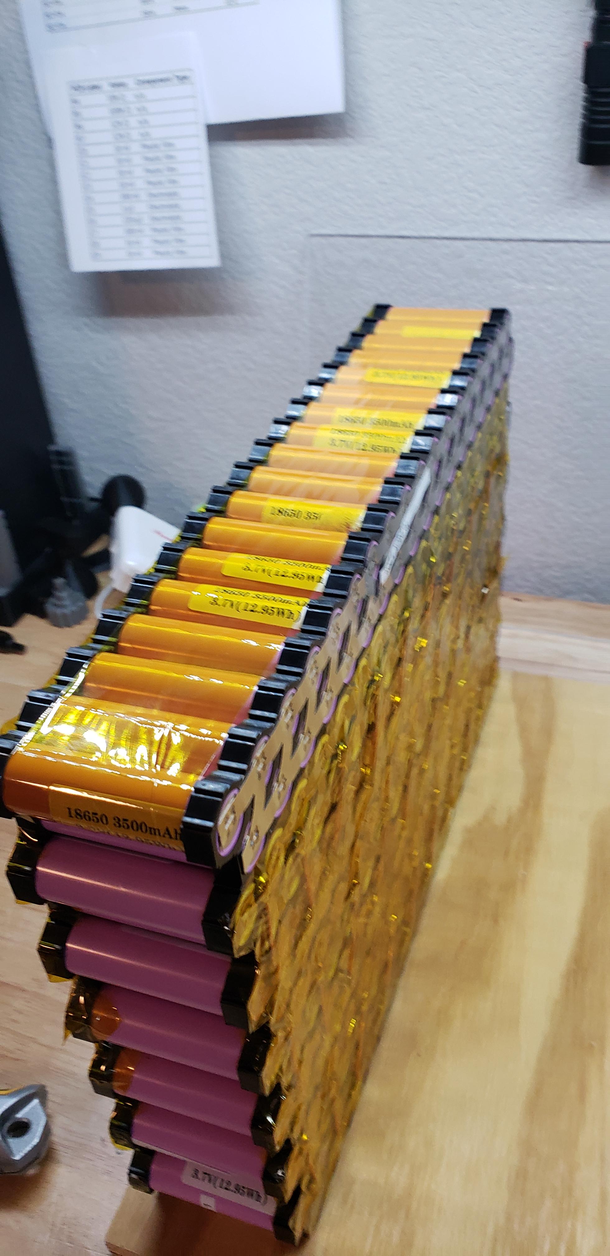
Hi, I'm building a 36P 14S portable battery using brand new Samsung INR18650-35E cells, and I would really like some help with brainstorming on how I can move forward from where I got stuck. This portable build is my first and I am taking it on as a learning experience, and as a precursor to eventually constructing my own home battery system.

I am specifically looking for feedback in regards to item #2 from the "potential solutions" section below, but I welcome any and all feedback!

Project Goals
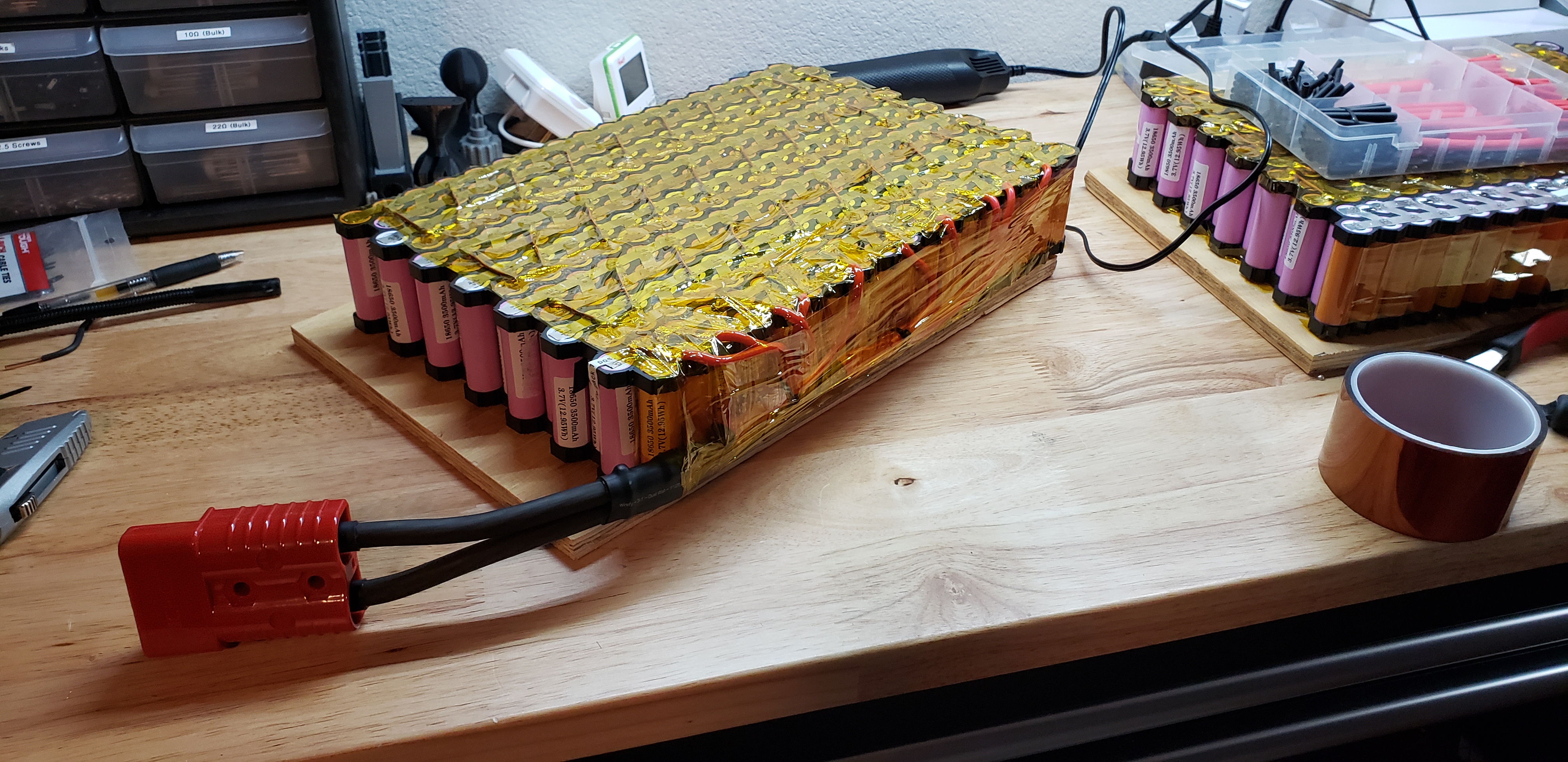
I want to have the ability to draw up to 30A @ 120V continuously from a portable battery that I can take camping and use to power my home in an emergency situation. I have a 3.5kW continuous/7kW peak 120V AC inverter. My use cases should never draw 30A for any meaningful amount of time, and I don't plan to actually put a 30A load on the battery, but that is what I began designing it to realistically support. With a 30A load, this will draw roughly 86A from the DC side, including a worst case 15% inverter inefficiency loss, so each series connection needs to be able to support at least 86A continuous.

86A split up in a 36P array is roughly 2.4A per cell, or approximately 0.685C. I feel that while these low C rates for the cells will be good for them in the long run, I'm really limiting the instantaneous power I can get out of the battery. Therefore, I want to build the battery from the standpoint where I can simply upgrade the inverter in the future and support higher loads, so I'd like to over build the internal wiring. I would like to be able to support up to ~1.6C, or 5.59A per cell, or just over 200A for each parallel string in the pack.

So, I've shared how the battery will actually be used, but also shared the specifications that I want to build the battery to which will allow me to simply upgrade the inverter in the future to get a higher output.


The Problem..
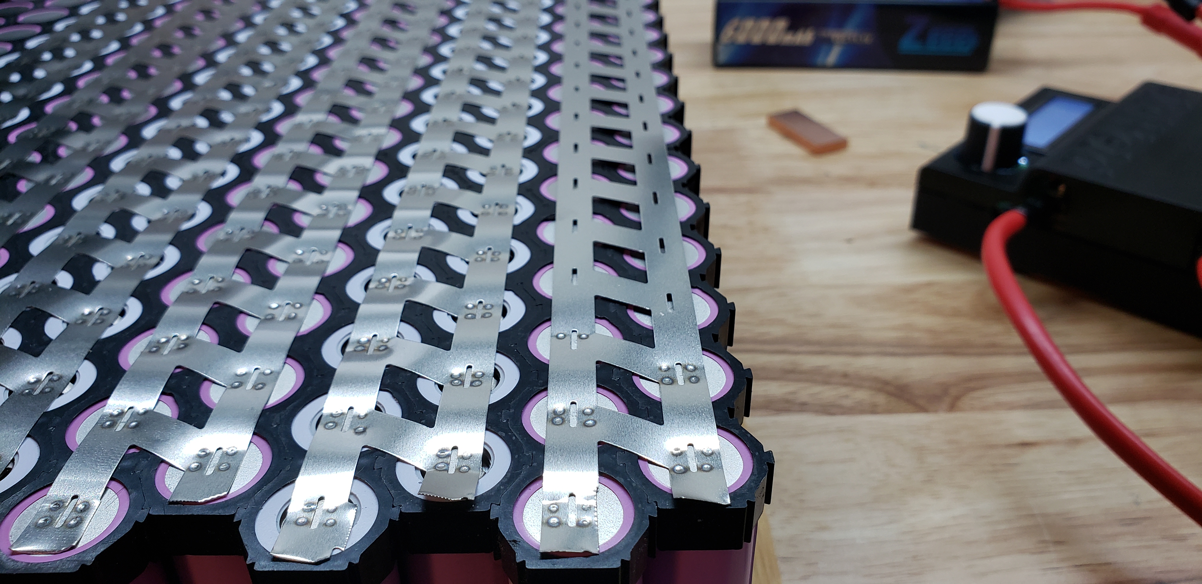
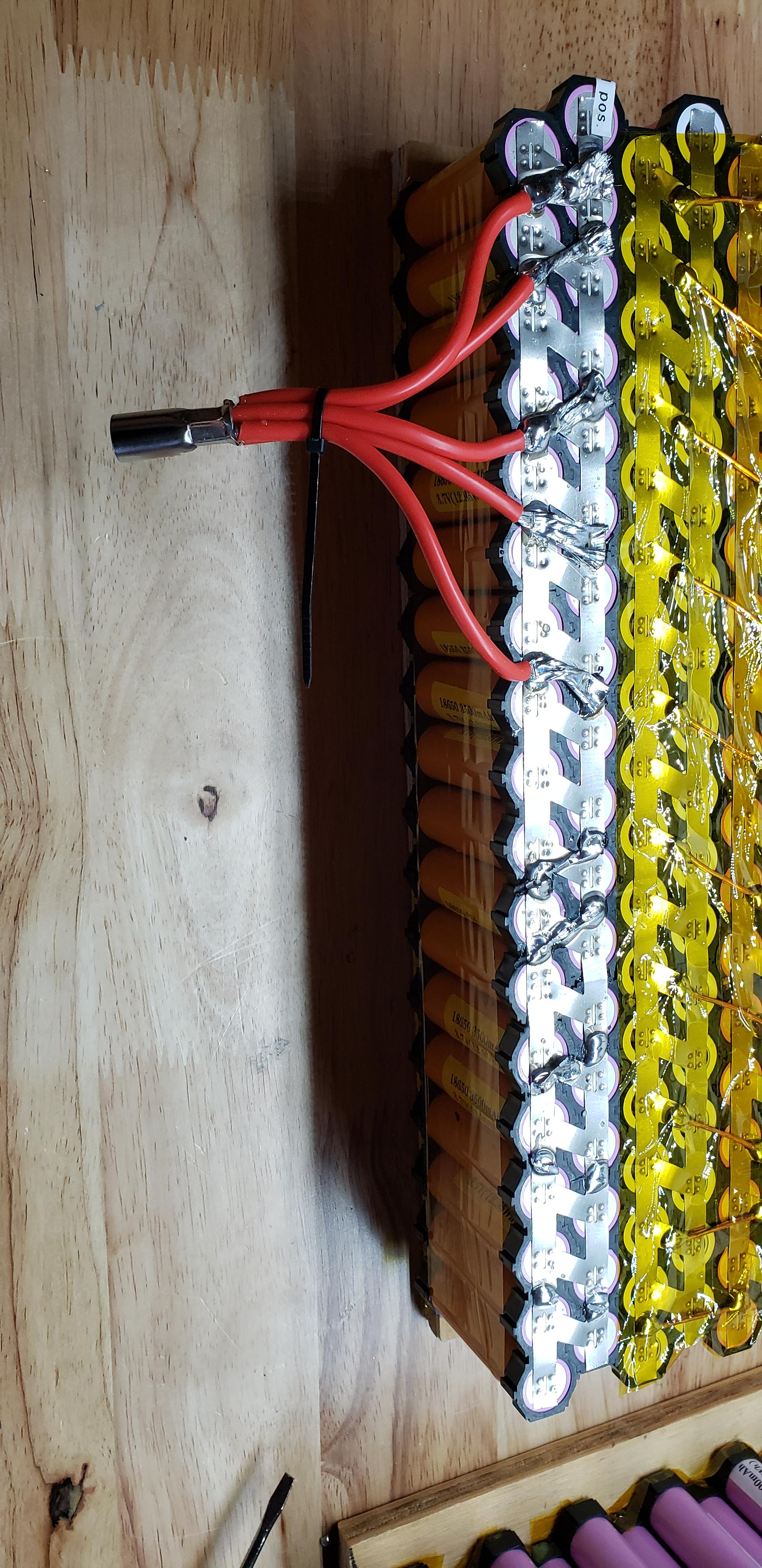
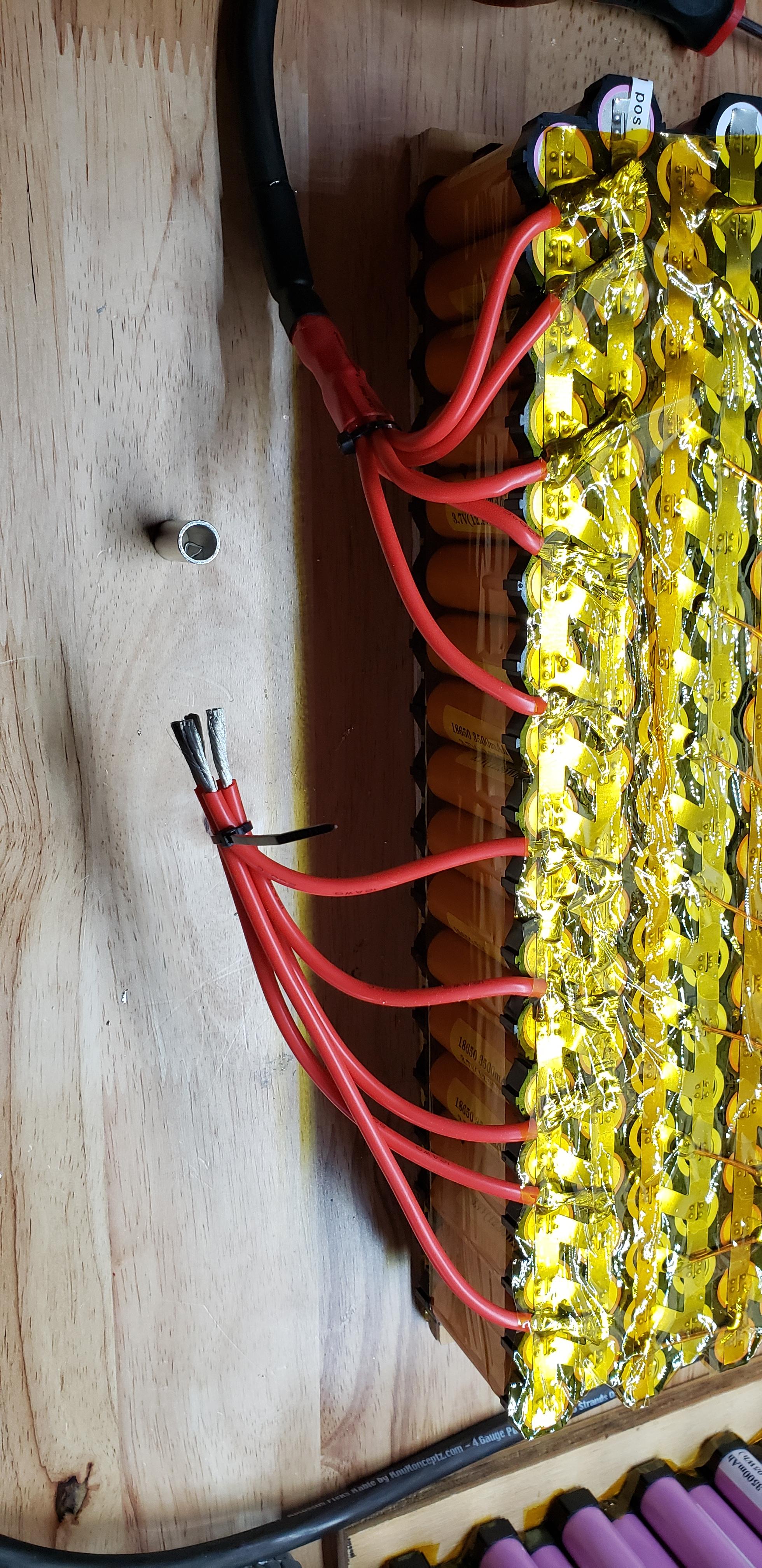
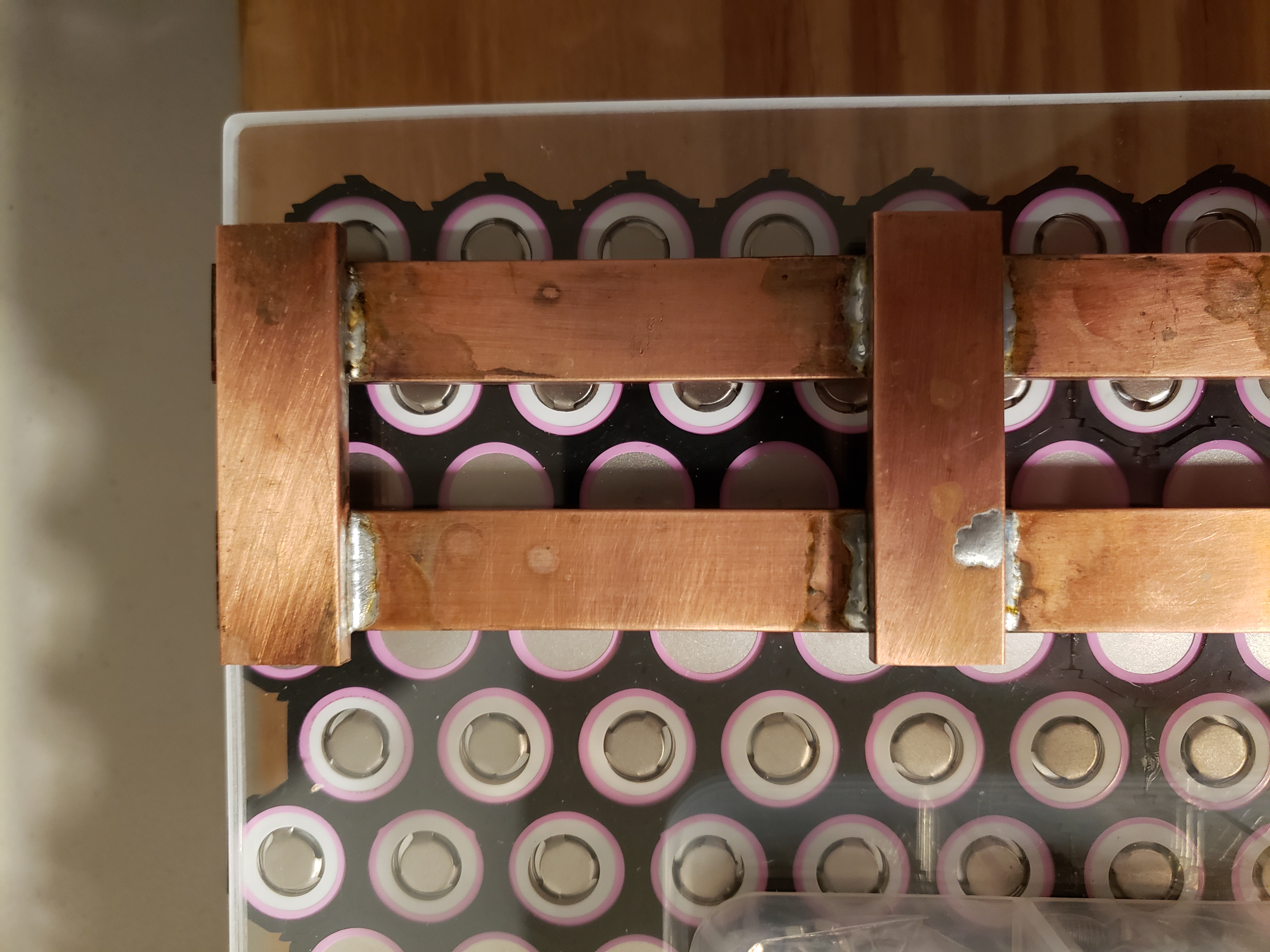
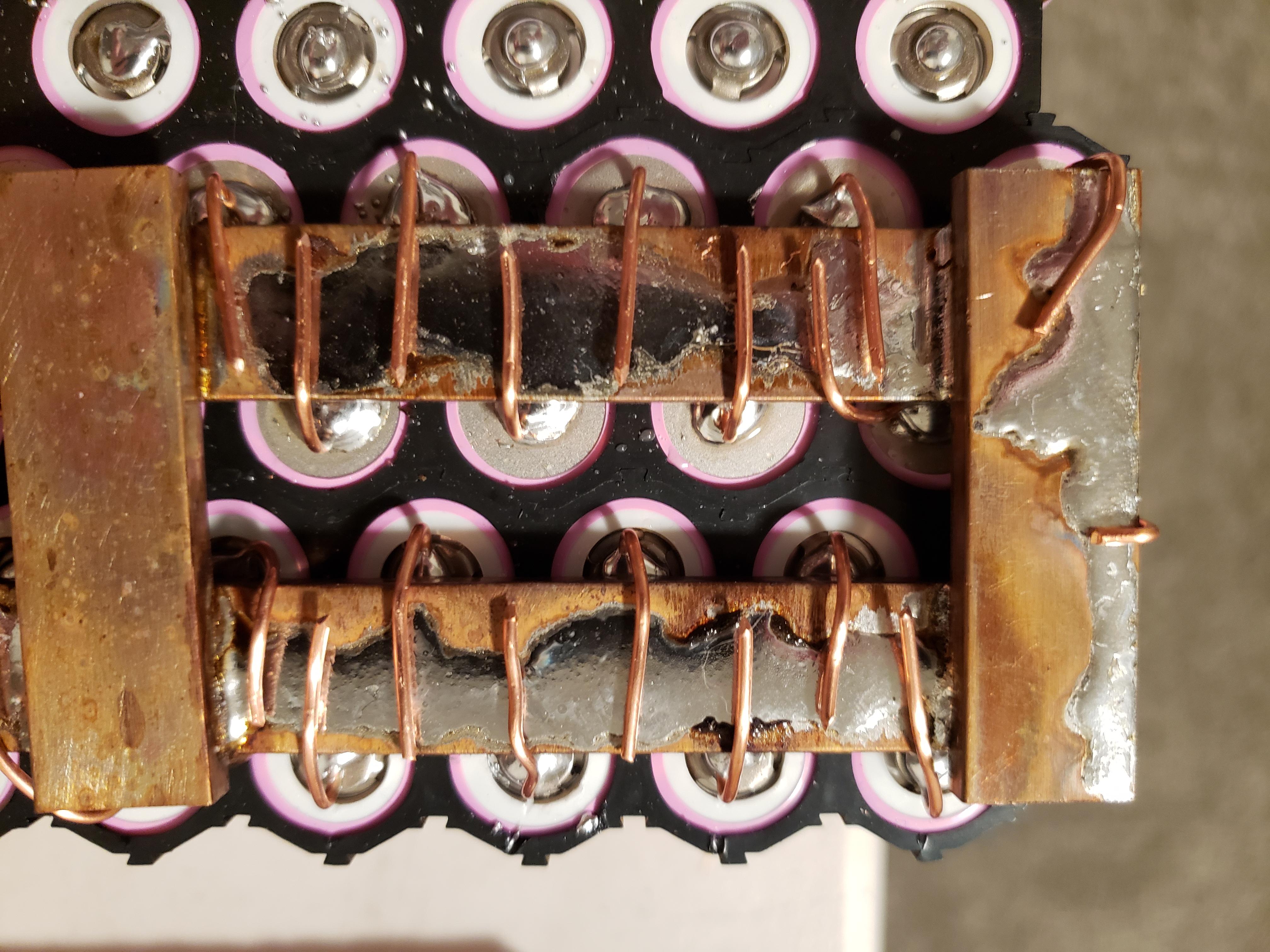
I had everything planned out and ran into some complications with the individual cell wiring during the build. The original plan was to wire each cell to a copper bus bar via 16AWG copper wire. Then, the series connections would consist of 5 short pieces of copper bus bar to bridge between the bars handling the parallel connections. Here's an example of the bus bars I cut and soldered - note that the copper wiring to connect each cell to the bar isn't shown. This is one bus bar assembly that connects the + side of a 36P string to the negative side of the adjacent 36P string.
TXBdZaB.jpg


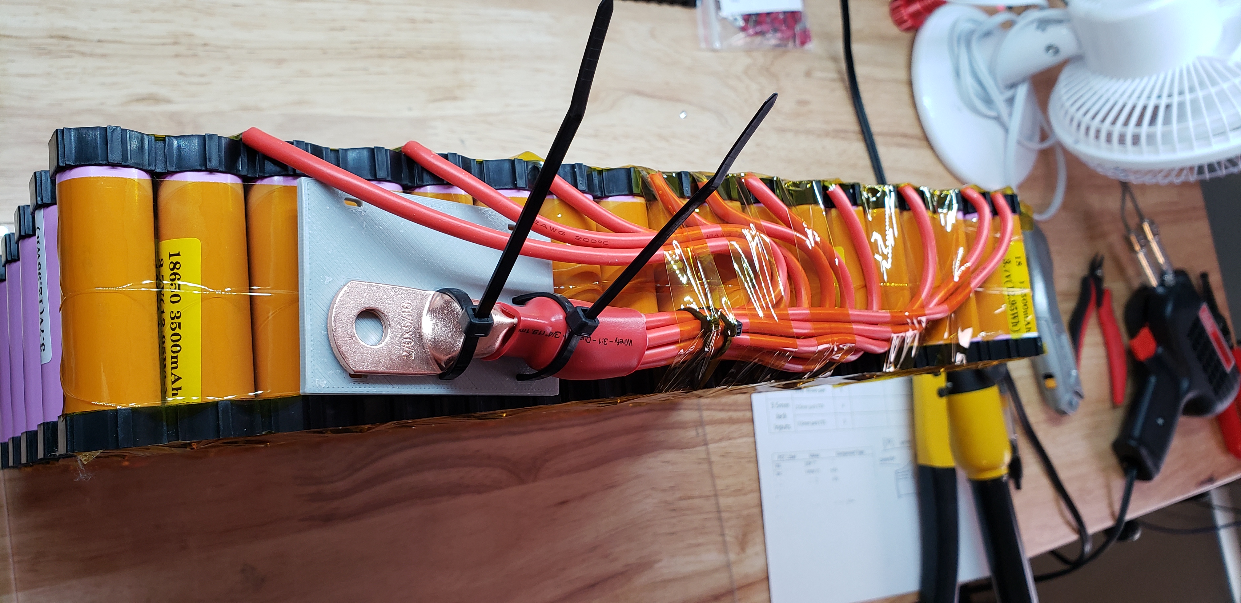
The problem came up when I tried soldering copper wire onto the bus bar. The bars soak up too much heat, and I can't get them hot enough to melt the solder - even with my Weller 240W soldering gun. I soldered the bus bar assemblies with a torch, but obviously I can't do that on the pack itself!

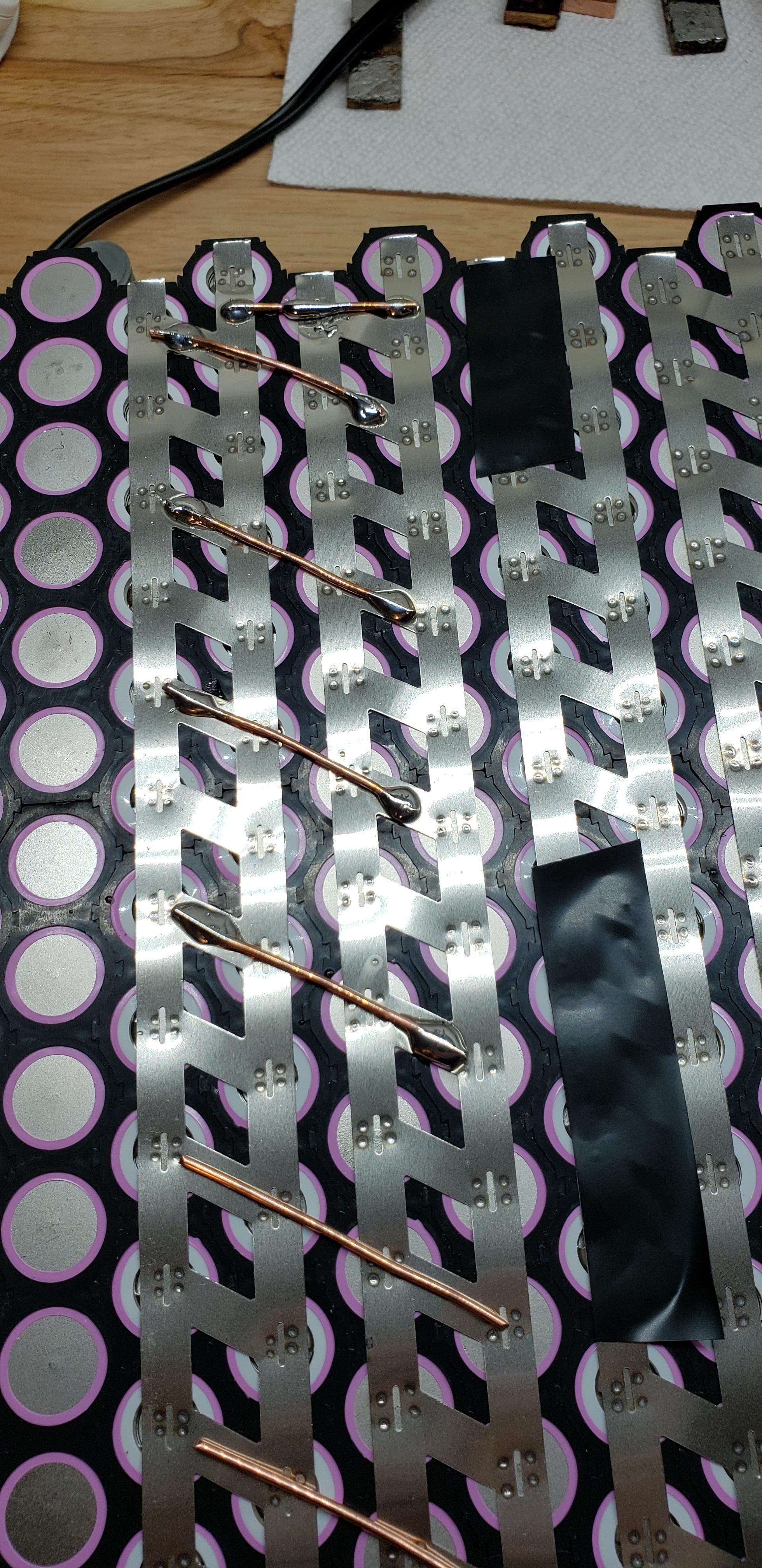
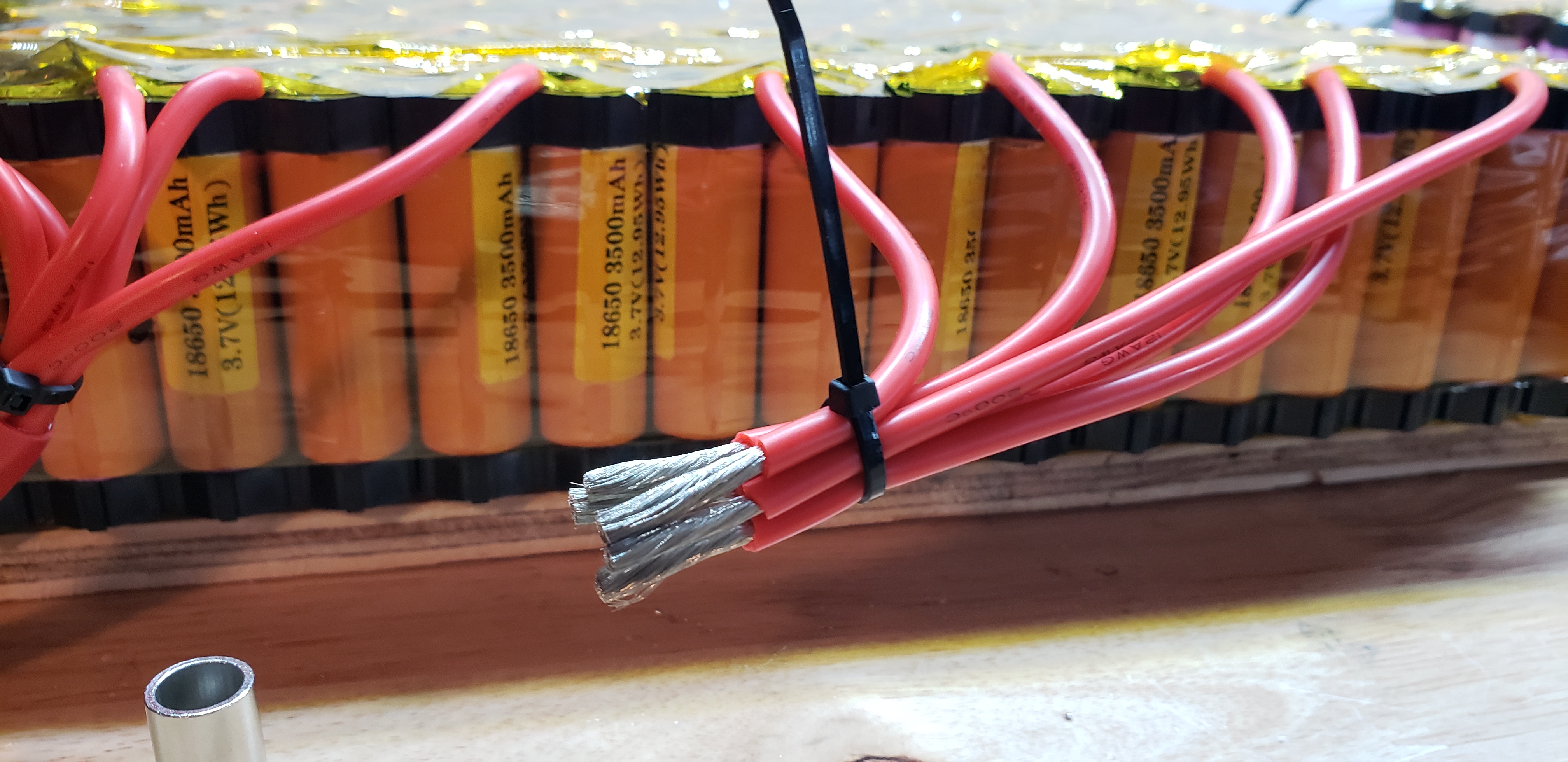
Specifically, the problem is attaching these wires to the copper bus bar. In this photo, I tinned the copper bus bar outside with my torch thinking it would help the solder melt with my soldering gun, but when I went to solder the wires onto the tinned copper, copper just disperses heat faster than my soldering gun can warm it.

dMhsq21.jpg


Potential Solutions..

1) A friend of mind suggested that I drill and tap the copper bus bars and use another piece of copper bar to clamp the wires between. I'm not particularly fond of this idea because that is a LOT of drilling and tapping, but also because I would not be comfortable with a mechanical connection that could come lose over time as the pack warms and cools. Loctite may help ease that concern, but I think there are better solutions.

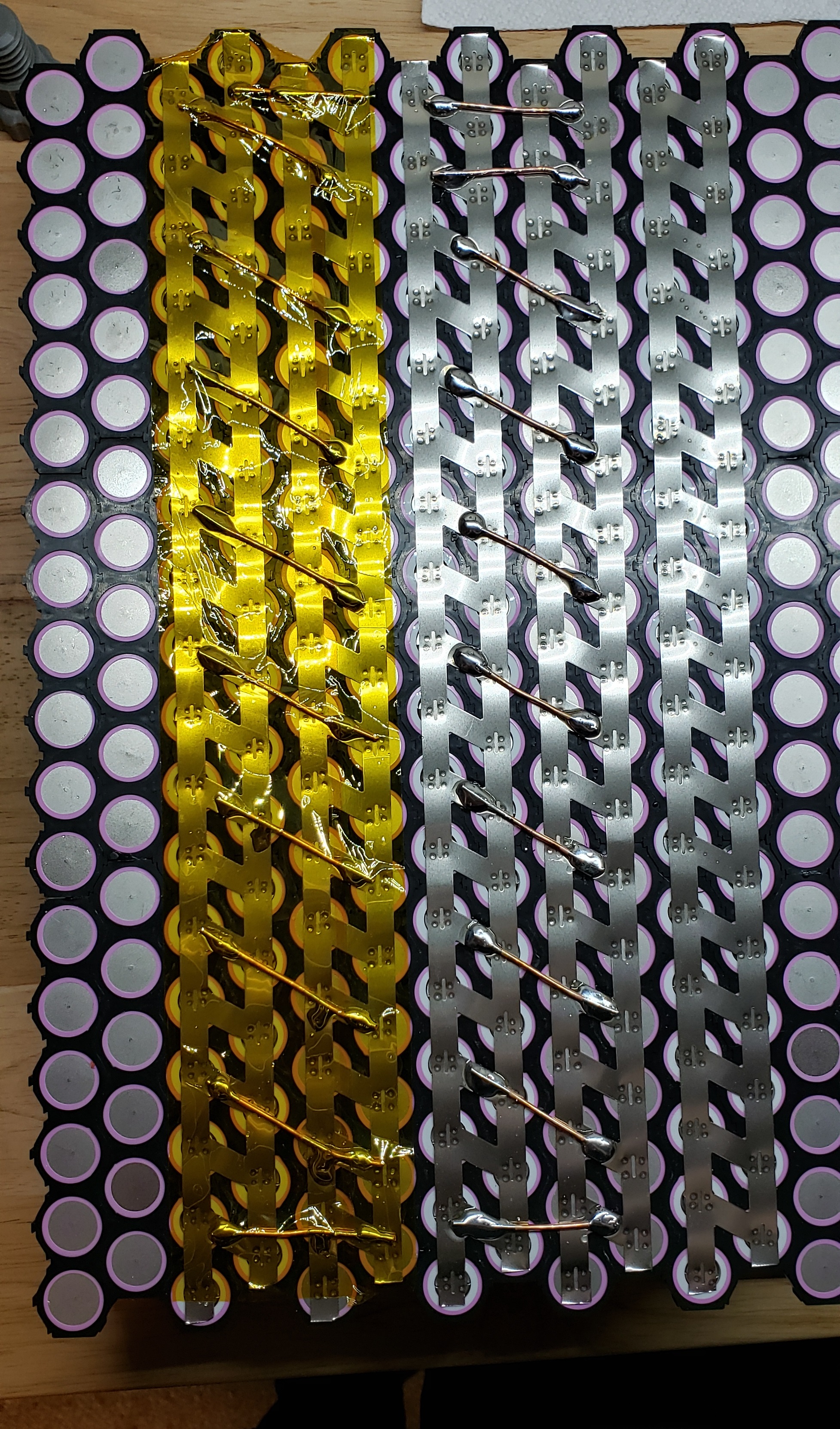
2) I revisited the idea of using nickel strip for the parallel connections. In my search for nickel strip ampacity, I came across this post where forum member spinningmagnets shared the idea of using what they call a "collector" at the end of the nickel strip. According to the ampacity charts in that same thread, I would be fine using a 0.2mm thick x 7mm wide nickel strip (or a 2P strip where 7mm is the smallest width). However, I'm unsure how the nickel strip would handle the current at the "collector" if there is upwards of 200A on a series connection. This is an example of what I'm thinking, with some spare 2P strip I had on hand and a scrap piece of my copper bus bar:

xykpMFS.jpg


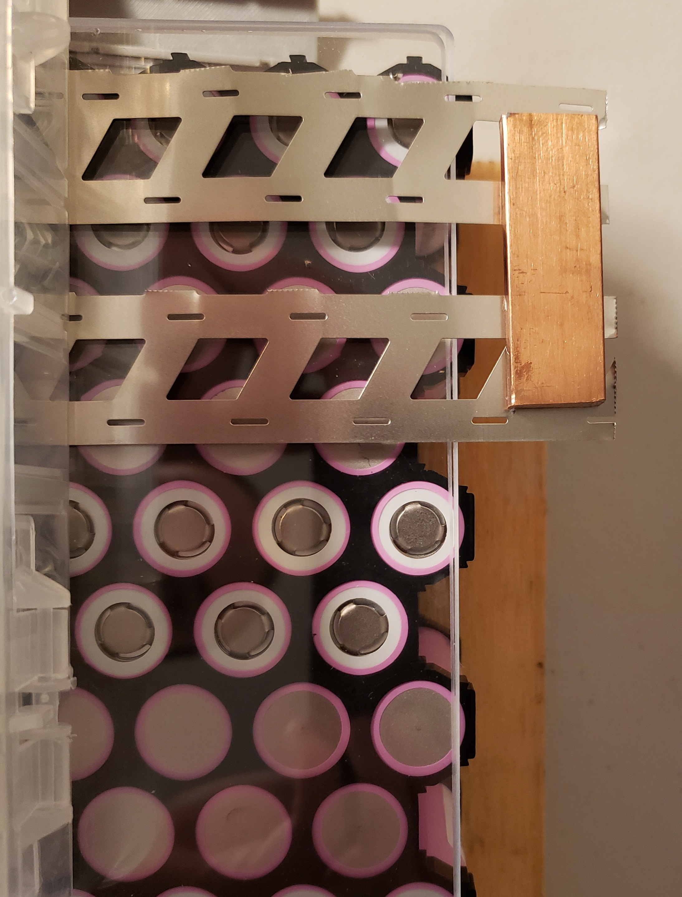
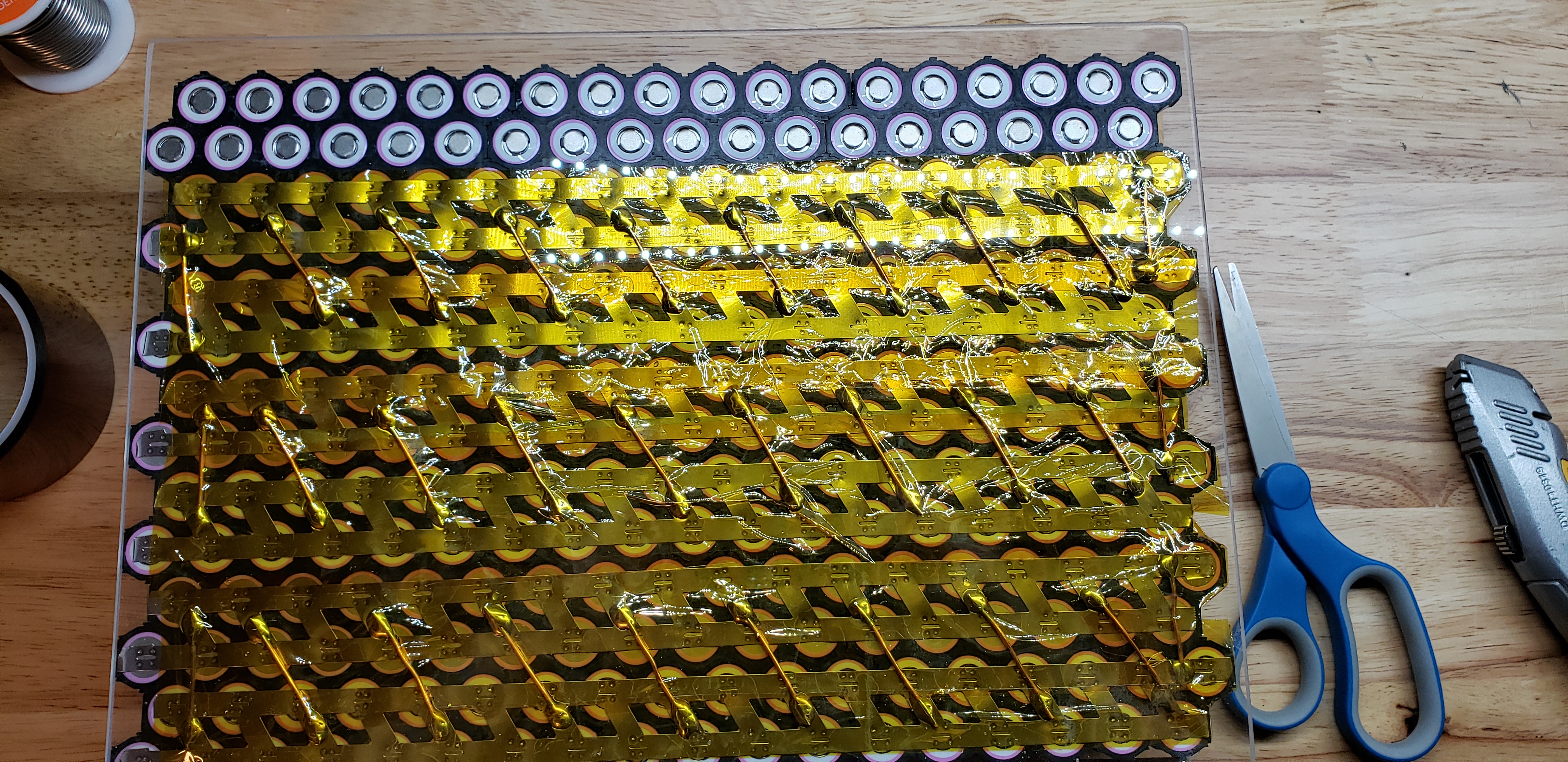
Wouldn't the small bit of nickel strip that is exposed between the copper bus bar and the first couple of cells also experience the full amount of current from the series connection? I understand that all members of a parallel group split the total system current evenly (well, in theory, anyways), and that a series connection will see the full amount of current. What I don't get with this collector idea is that if the full amount of current (say, 200A) travels through the bus bar link between the nickel strips, it surely doesn't just stop being 200A when it touches nickel! Wouldn't I need to add more copper to the serial connection, like this?

1NYptmb.jpg


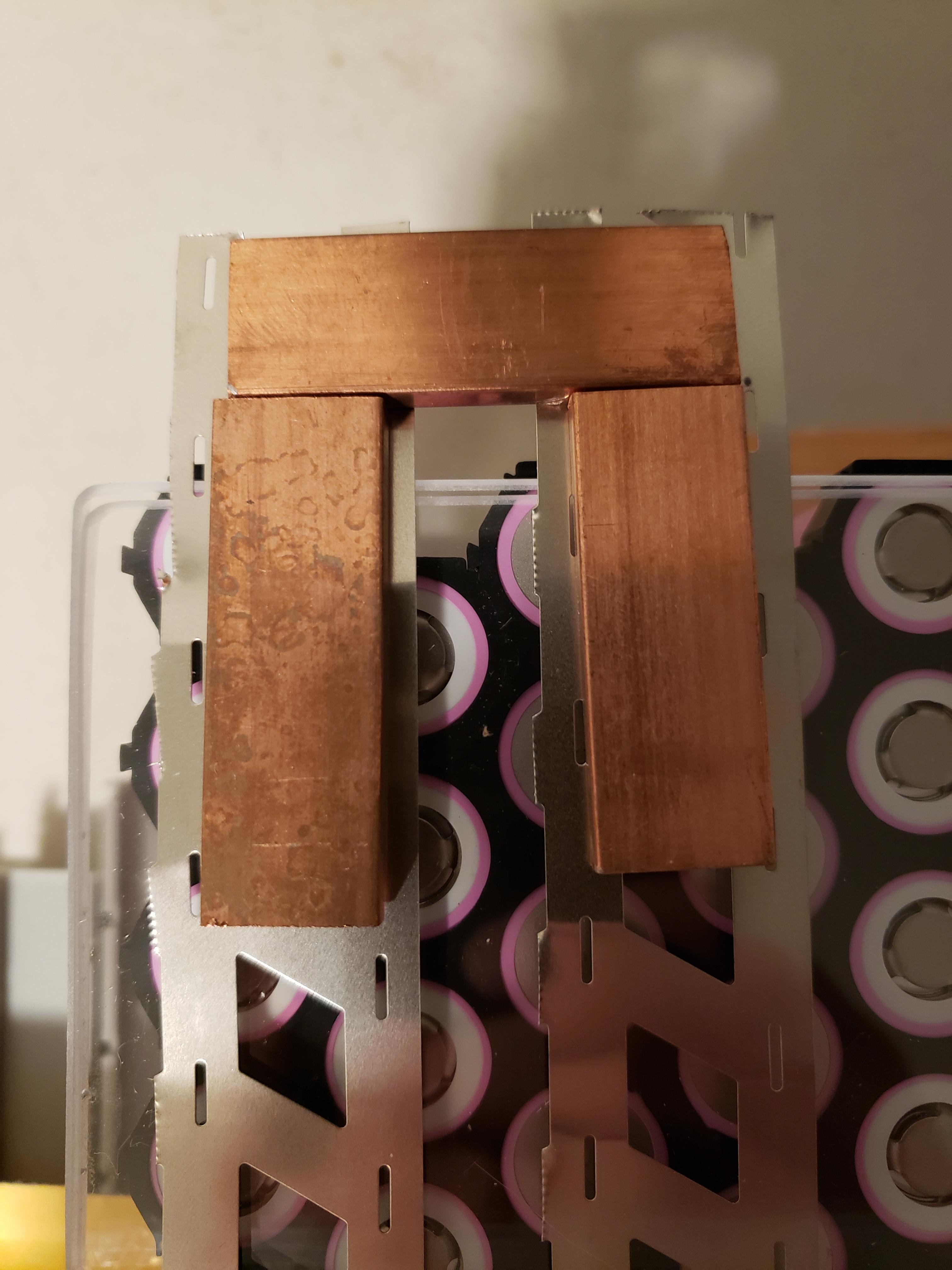
Or, could I add additional serial bridges between the nickel strip, like how I did with my original bus bar design?

Thanks so much for your time!
 
If you can, try some solder flux pen or paste on the bus bar, really get a lot on it.
Also, did you clean the bus bar with isopropyl alcohol?
Try different solders on a scrap piece.
 
Markz, thanks for your input. I did not clean the bars using isopropyl, but I did use a lot of flux when torch soldering the buss bar assemblies. Afterwards, I cleaned the buss bar assemblies with a wire brush and soap and water. I have thought about trying soldering paste for its lower melting point but haven't yet - I just ordered some ChipQuik paste so I will try that when it arrives.

Any idea about using the "collector" in combination with nickel strip? Being able to do that would really simplify my build and save me a good amount of weight!
 
Hi David,
do you have a spot welder?
For 200A and 36P (in your case 18p x 2) it would be be sufficient using one big nickel strip with 0.15mm and i think even the one you have would be already enough (if it is pure nickel with 0.15mm).
The distance the current has to flow through those connections is so short that it will not add much to the total resistance of your battery (voltage sag) and you won't notice if you have 1% or 0.5% lower resistance.

On + and - side i would solder 13AWG (or 2.5mm) to the nickel strip beween very second cell or so, all with same length, so you would have 8 in parallel put together.

Using those large copper bars is totally overkill IMO and if you solder on the cells for too long time you might do nothing good and get other problems later.
 
madin88 said:
Hi David,
do you have a spot welder?
For 200A and 36P (in your case 18p x 2) it would be be sufficient using one big nickel strip with 0.15mm and i think even the one you have would be already enough (if it is pure nickel with 0.15mm).
The distance the current has to flow through those connections is so short that it will not add much to the total resistance of your battery (voltage sag) and you won't notice if you have 1% or 0.5% lower resistance.

On + and - side i would solder 13AWG (or 2.5mm) to the nickel strip beween very second cell or so, all with same length, so you would have 8 in parallel put together.

Using those large copper bars is totally overkill IMO and if you solder on the cells for too long time you might do nothing good and get other problems later.

Thanks madin88. I do have a spot welder (the cheap DIY one from Banggood), but I am planning to get a Kweld unit if the DIY one doesn't work out well.

The strips I have are in fact 0.15mm, but they were actually 4P strips that I cut in half for the visual example in the pictures I shared. I will have to acquire some 2P nickel strip to spot weld. I'd prefer to go with the thicker 0.2mm to support higher outputs in the future. Should I use solid nickel strip that is wide enough to cover the 2x18 row, or should I acquire honeycomb style strips with the cutouts that help make spot welding easier? I completely understand the difference in capacity capabilities and how the honeycomb style strips will have more choke points for current flow.

You make a good point about using multiple 13AWG wires. I see that 12 GA wire is good for up to 25A for short runs, 13 AWG is likely around 22-23A, and 8 of them would allow for up to (22 * 8 ) = >200A of current to flow across the series connections between the rows of + and - terminals.

I agree that the original copper bar idea is extreme - even laughable, now that I think of it! :lol: I just read spinningmagnets article and he suggests to never solder onto the negative terminal. Well, any damage is already done, so I'll have to either try spot welding onto the tinned solder pads, or removing the solder humps on the cells without heat. Luckily, I only soldered one side of one of the packs, so it's not a huge mistake.

Thanks for your input! Your idea seems obvious now that I'm looking back at it - I was so focused on the large amount of current from my load calculations and over-engineering the wiring.
 
Yeah the maximum current demand of your system is unlikely to ever need that much conductor.
One option might be to solder nickel tabs to the copper busbars and spot weld the tabs to the cell tops.
 
Gents, thanks so much for your feedback! I cleaned up the terminals on the side of the pack that I pre-soldered so I should be ready for spot welding nickel strips now. I was weary of using heat to remove the solder from the terminals, so I used my Dremel with a cutoff wheel to clean the terminals up.

I had trouble finding 2P honeycomb 0.2 x 19.5mm pure nickel strip, so I ordered some direct from a manufacturer in China. I'm waiting on that to arrive and then I'll be able to proceed with the build.

I will follow up periodically on the progress of my build with photos showing the resolution to the original problem in case it helps anyone in the future.
 
I wanted to follow up with progress of my build so that this thread can hopefully be of value to others in the future. I do want to preface this that I am an amateur and there are likely many areas where I could have done things better, and I welcome any and all feedback and criticism so I can improve my technique for a possible future build.

So, I received my 0.2mm nickel strip and went to try spot welding it... I was powering my cheap banggood spot welder using a brand new motorcycle-sized 12V lead acid battery but it just didn't have the juice. So, I just decided that I have way too much spot welding to do to *** around with cheap tools, and I ordered a K-Weld unit along with a 11.1V 3S 6Ah 80C battery pack from Amazon. This spot welder and battery combination worked wonderfully well, giving me between 1150-1250A of current in each spot weld for up to about 275 spot welds before its current output began to drop off. I was able to get about 10 spot welds in a row until the spot welder's leads and battery pack got too warm for comfort, so it was a slow process.

Without further adieu... here are some photos of the build progress. The entire album is here and contains some detail about each photo.
https://imgur.com/a/dKNHliU

zbSACiu.jpg


sSc4Ios.jpg


U9GG2f4.jpg


VZJ8EbT.jpg


lWq32er.jpg


sIZBvlD.jpg


qOzu02b.jpg


kjJ1M3o.jpg


dOSuXes.jpg


irmItmN.jpg


4RrC6Fd.jpg


Still to do...

I still have quite a lot left to do. BMS wiring/programming, solar charge converter, 48V to 12V buck converter and 12V accessory bus, power monitor, fan controller, and additional temperature sensors for each pack so I can keep a close eye on temps.

More updates to come!
 
Awesome! you're doing about the same thing that i am going to do, but you are building your pack to be able to draw a bit more current than me. I am just going to take max 2,5kw (will use maybe 2kw) and you will as far as i understand it be using 3.2kw (120x30).

I will follow your build and post my own when it's time! I like your idea of copper rods/cable to connect the paralell packs, and especially at the positive output cable. i will need to concider that myself. i will need to draw around 50A per unit, so a little less than you, but still a very interesting idea!

cheers! =)
 
Wow! Very aesthetically pleasing workmanship. Great welds, soldering, crimping, attention to details.
 
MK2R said:
Awesome! you're doing about the same thing that i am going to do, but you are building your pack to be able to draw a bit more current than me. I am just going to take max 2,5kw (will use maybe 2kw) and you will as far as i understand it be using 3.2kw (120x30).

I will follow your build and post my own when it's time! I like your idea of copper rods/cable to connect the paralell packs, and especially at the positive output cable. i will need to concider that myself. i will need to draw around 50A per unit, so a little less than you, but still a very interesting idea!

cheers! =)

Very cool! The copper wiring to connect parallel packs was an idea that was suggested by madin88 in this thread because I was struggling with the idea in the first place. I'm sure it will work out well!

99t4 said:
Wow! Very aesthetically pleasing workmanship. Great welds, soldering, crimping, attention to details.

Thank you for the compliments!

markz said:
Did you add insulation rings to the 18650 before you slipped them into the holders and proceed to solder or tab weld?


Yes and no. You probably recall (since you were the first to reply to this thread) the way I was originally trying to handle the series connections with those massive bus bars being connected by individual wires soldered onto each cell. Well, removing those beads of solder from the cells was a bit of a technical operation with my Dremel since I didn't want to use any more heat, and some of the cell heatshrinks were nicked by my cutoff wheel. Because of this, I disassembled that pack and put the insulation rings on the positive ends of the cells. Luckily, I didn't solder anything onto the 2nd pack in my build, so that pack's cells' heatshrinks were not damaged in any way, and I left those as is.

Both packs in my build will have a 1/8" acrylic sheet above and below it to prevent anything from penetrating the heatshrink and kapton tape once the packs are in my enclosure. Is there another reason to use the insulator rings other than preventing shorts from foreign object punctures?

Edit: I just read through this thread and gained some more context. I should have put them in the second pack but I think given the nature of my build I'll be just fine. I called this a "portable battery" in my original post but in all honestly - for as much as I haven't traveled much lately - it's going to sit in one spot in the garage and be ready to power a future transfer switch panel. I suppose what I am getting at is that packs in ebikes that move a whole lot more are subject to a lot more wear and tear, and I absolutely see the benefit for insulator rings. High temperatures melting the plastic cell casings was mentioned in that thread too, and I am somewhat concerned about that given my tightly-packed honeycomb layout, which already has quite a bit of Kapton tape, and will be placed in a heatshrink bag. Even though my actual expected C rates will be no more than 0.7 per cell, I'll still be adding at least 2 temperature sensors per pack and installing a Raspberry Pi Pico with an LCD display next to my power monitor display to keep an eye on the actual pack temps. I am also putting in a fan controller, but it will really only be for the ambient air temperature inside the enclosure, not the actual pack temperature.
 
Excellent illustrated thread.
Re series connection differences: battery connections.jpeg

If you're already using a nice spotwelding setup for parallel connections, why solder copper wire every other for series connections instead of spotwelding? Could make up conduction difference by spotwelding on every instead of every other?

What crimper did you use for the Andersons? How does it compare to soldering them?
 
fatty said:
Excellent illustrated thread.
Re series connection differences:

If you're already using a nice spotwelding setup for parallel connections, why solder copper wire every other for series connections instead of spotwelding? Could make up conduction difference by spotwelding on every instead of every other?

What crimper did you use for the Andersons? How does it compare to soldering them?

Thanks for the information on the difference in connections!

To be honest, I didn't even think of spot welding the 14awg series connections at the time. I just tried it on some spare nickel strip though, and it's actually a bit difficult. The spot welder's electrode tips are round, and the wire is round, so it's hard to put enough pressure on the 14awg bridge without it shooting out from underneath the electrode tips. Also, since the spot welder's electrodes are on the same side of the nickel strip (ie, one on the wire, and one on the nickel strip right next to the wire), there's no real way to actually make the weld at the place where the copper wire meets the nickel. My attempts ended up basically zapping a hole out of the nickel strip and not really doing anything to the copper wire. Now, if I could get an electrode on opposite sides of the nickel strip (ie, one electrode on the copper wire, and one on the opposite side of the nickel strip exactly where the copper wire meets the nickel, that would probably work much better. But that's not possible when the nickel strip is already welded to the battery terminals.

The crimper I used is a 10-ton hydraulic crimper with a set of hexagonal die. $50-60 bucks on Amazon and it actually works quite well. I preferred crimping the connectors on instead of soldering them because I wanted more mechanical strength from the joint. I've soldered 2/0 awg connectors in the past and it is much trickier, requiring a torch, a LOT of solder, and lots of caution. However, with this battery build project, I'm concerned about thermal expansion and contraction over the 7-10 years I predict the battery will last, so I wanted to eliminate any possibility of major connection points coming loose.
 
David01 said:
To be honest, I didn't even think of spot welding the 14awg series connections at the time. I just tried it on some spare nickel strip though, and it's actually a bit difficult. The spot welder's electrode tips are round, and the wire is round, so it's hard to put enough pressure on the 14awg bridge without it shooting out from underneath the electrode tips. Also, since the spot welder's electrodes are on the same side of the nickel strip (ie, one on the wire, and one on the nickel strip right next to the wire), there's no real way to actually make the weld at the place where the copper wire meets the nickel. My attempts ended up basically zapping a hole out of the nickel strip and not really doing anything to the copper wire. Now, if I could get an electrode on opposite sides of the nickel strip (ie, one electrode on the copper wire, and one on the opposite side of the nickel strip exactly where the copper wire meets the nickel, that would probably work much better. But that's not possible when the nickel strip is already welded to the battery terminals.
Oh, sorry -- I didn't mean spotwelding the copper wire. I meant why not spotweld nickle strip for series connections? This seems much more common than soldering copper wire for series connections -- that's quite atypical in an otherwise strip spotwelded pack.

David01 said:
The crimper I used is a 10-ton hydraulic crimper with a set of hexagonal die. $50-60 bucks on Amazon and it actually works quite well. I preferred crimping the connectors on instead of soldering them because I wanted more mechanical strength from the joint. I've soldered 2/0 awg connectors in the past and it is much trickier, requiring a torch, a LOT of solder, and lots of caution. However, with this battery build project, I'm concerned about thermal expansion and contraction over the 7-10 years I predict the battery will last, so I wanted to eliminate any possibility of major connection points coming loose.
Cool -- $50-60 -- not great, but not terrible. I worry about my preferred eutectic solder on marginal current capacity terminals.
 
fatty said:
Oh, sorry -- I didn't mean spotwelding the copper wire. I meant why not spotweld nickle strip for series connections? This seems much more common than soldering copper wire for series connections -- that's quite atypical in an otherwise strip spotwelded pack.

Oh! Well that's easy - that's because I am building the battery so that all the wiring and components can support each cell being safely loaded to ~1.55 C. Even though that's a relatively low C rate from the cell's perspective, that will be about 200A of current on the DC side. And since series connections see the full amount of current, there's no way nickel strip on the series bridges could support 200A. But, ten individual 14awg wires will be able to support up to 200A.

Just for context... An 8.4kW load on the AC side (~70A @ 120V) will present about a 200A load on the DC side. I don't actually plan on trying to put an 8kW continuous load on the battery. In fact, the inverter I've chosen is only a 3.5kW / 7kW rated inverter. I just wanted to build the battery so that the battery packs are not the limiting factor in my build. If I want to upgrade the inverter in the future or hookup the battery to a larger external inverter, I can, without having to replace anything inside the battery. I'd rather keep the cells (my main investment!) safe and stress the inverter out, than pair it with a high capacity inverter and stress the cells out. This will also keep the battery safer when handling inrush current surges from inductive loads. Now, let's just hope my inverter is up to the task!
 
David01 said:
Oh! Well that's easy - that's because I am building the battery so that all the wiring and components can support each cell being safely loaded to ~1.55 C. Even though that's a relatively low C rate from the cell's perspective, that will be about 200A of current on the DC side. And since series connections see the full amount of current, there's no way nickel strip on the series bridges could support 200A. But, ten individual 14awg wires will be able to support up to 200A.
Ah, thought so. I expect you ran the numbers on nickel strip current capacity -- would you mind posting what you found?
 
fatty said:
Ah, thought so. I expect you ran the numbers on nickel strip current capacity -- would you mind posting what you found?

I did - I found this post on the forum here with a chart compiled by forum user Matador.

I went with 0.2mm pure nickel strip, and the "thinnest" parts of the nickel strip are about 7 or 8mm. So, according to his chart, my 0.2mm thick nickel strip is good for up to 5.7 - 6.4A (depending on how I measure the width). At the peak hypothetical load that I'm building my battery to (~200A @ 48V DC), the maximum amperage on the parallel connections will be about 5.6A. (200A on a series connection split by 36 cells in parallel is 200 / 36 = ~5.55A).

Huge thanks to Matador for compiling that extremely valuable data!!
 
Back
Top