Sorry for asking as this has no doubt already been addressed (can't find) but what would be the best cheap and easy resistive device to put between alligator clips to manually bleed charge off, say, a 5p 18650 cell group? I'd think 5A would certainly be a safe current draw and my Imax B6ac is limited to 2A. Very slow.... Probably a 15 or 20W incandescent bulb?
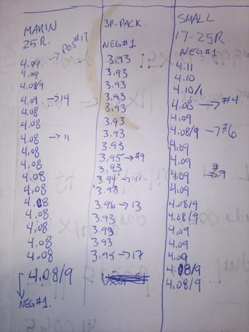
I'm still testing my no-weld 20s5p design. Intentionally going without BMS. Going great so far and pack is pretty well balanced but need to quickly knock .15V off a couple groups to get whole pack to full charge.
And on a related note, is it pretty common for the most negative and most positive cell groups to tend towards a slightly higher V during charging? I'm using an 84v 3A Yarlan charger btw... probably getting a 5A version soon...
")