Battery design advice required

darthpaul93

1 µW
Joined
Feb 16, 2021
Messages
1
I’m thinking of having a go at building up a battery pack. Something to do until lockdown is lifted! Pretty much decided on 21700 cells for a 14s2p pack to go in a saddle bag. Obviously easiest deign is 14 cells long 2 cells high when looking at the cell ends, but that’s too long for the bag. So I want to split it and essentially fold it on itself so it will be 7 long 4 high. But then how do I connect the series connection together that is now split? Two thoughts were double up the nickel strips across the two parallel connections that are now side by side or something like a 12 gauge wire to connect the two parallel strips together?
Any ideas or suggestions are appreciated.
 
I'm doing a 14s2p in a 7x4 configuration.

My plan (and would love feedback here) is do this:

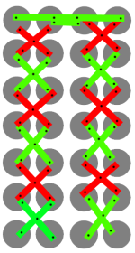
14s2p-4x7.png

Green are strips on top, red are strips on bottom, black dots are weld points.

You can see at the split/fold (top of the picture), I intend to weld the inner two cells with a strip, and the outer two cells with a separate strip. The two strips would be overlapping; I've shown them slightly staggered here for clarity, in reality they will not be.

The idea is that each strip is directly welded onto the cell it is responsible for (nickel-nickel welds suck!), and the top strip (the longer one) will have two additional welds onto the lower strip over the inner cells. Those additional welds will be weak, but they are not critical since the upper strip is laying on top of the lower strip, and this path will only be responsible for the low-current balancing of the parallel cells.

My reason for going with an X pattern is similar: less welds, no layering, same series ampacity.

WARNING Do not just copy me, as I have no idea what I'm doing. This is my first build. I think this is a good idea, but I would love for someone more experienced to poke holes in this plan. Thanks!
 
Maybe just me but I'm not grokking how that graphic ends up as 2P.

Are the cells all "pointing" pos/neg the same direction, or alternating each pair or?

Maybe mark pos/neg ends?

Sent from my Nexus 6 using Tapatalk

 
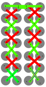
Here's a revised version with the polarities marked (for the "top" end of the cell that you can see in the diagram):

14s2p-4x7.png

For the bottom right group, I've shown the parallel path in blue, and the series path in magenta.
 
cellmate said:
My plan (and would love feedback here) is do this:
The nickel layout is fine but not ideal (diagonals are longer than direct, so will have slightly more resistance), you just need to make sure you use enough nickel for whatever current you plan running and it'll be fine.
 
Thanks serious_sam!

I think I'm okay for quantity of nickel. I'm using 8mm x 0.2mm pure nickel, and the battery will drive an TSDZ2 which can only sustain 16-20 A continuously, so 8-10 A per strip.

If I did the math right, it looks like the additional losses from the extra distance are pretty much negligible in this battery:

Code:
2.5cm (diagonal): R = 0.0010688 ohm
    Power loss per strip:           10A^2 * R = 0.10688 W
    Number of strips in series:     12
    Total resistive loss:           1.28 W
    Total power at 52v:             520 W
    Percent loss:                   0.25%

1.8cm (straight): R = 0.0007695
    Power loss per strip:           10A^2 * R = 0.07695 W
    Number of strips in series:     12
    Total resistive loss:           0.92 W
    Total power at 52v:             520 W
    Percent loss:                   0.18%

So we're talking about a 0.07% difference in overall battery efficiency. Seems worth it for the savings in labor and increase in reliability (no layering).

Nickel resistance values came from an online calculator.
 
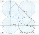
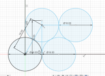
looks like just as much nickel needed doing an "x" as done when doing the typical square IF you orient all the cells staggered instead of in rectangular pattern as in your pic. dont know why you write .07% which is a tiny amount. doing the x on the rectangularly arranged cells would be 30% more strip needed and 30% more resistance.
 

Attachments

  • Capture.PNG
    Capture.PNG
    35 KB · Views: 615
  • Capture 2.PNG
    Capture 2.PNG
    29.5 KB · Views: 615
Hummina Shadeeba said:
IF you orient all the cells staggered instead of in rectangular pattern as in your pic. dont know why you write .07% which is a tiny amount. doing the x on the rectangularly arranged cells would be 30% more strip needed and 30% more resistance.
If it were a triangular pack and bus bar length was a major consideration for best raw performance then why even consider a typical square layout? However, from the rectangular design that's NOT the case.

This X bus bar design suggests severe pack vibration and cell spacing for cell wrap cushioning. Maybe, the extra nickel strip resistance (30%) is not as high of a priority for this battery application as for the raw performance of a Monster Mountain Bike ?
https://endless-sphere.com/forums/download/file.php?id=287983
Then again maybe we're making too big a deal about 30% more resistance with X design. Depends on application even if its design is for raw performance
 
i dont think people make batteries in a rectangular pattern like the drawing of the original poster. maybe they do. a waste of space and not as strong as the triangular id think in most cases. rather make a solid smaller block unless had mounting posts between. if its triangular cant do the x pattern without increasing strip. or maybe not and i have the wrong part measured


im thinking of making my next pack with just nichrome wires for all the balance connections. it should get hot if some cell is very imbalanced and ignite the firecrackers i will place in between cells. for safety to warn me if i might have a fire.
 

Attachments

  • Capture.PNG
    Capture.PNG
    33.7 KB · Views: 596
Code:
dont know why you write .07% which is a tiny amount. doing the x on the rectangularly arranged cells would be 30% more strip needed and 30% more resistance.

Yes, it is 30% more nickel and 30% more resistance. My calculations showed a 39% increase in losses (1.28 Watt vs 0.92 Watt).

The 0.07% figure was for efficiency of the overall battery. At 10A and 52V (per series) it should be able to deliver 520W of power, but is losing either 1.28W or 0.92W to heat in the nickel, depending on layout. In the big picture of the entire battery, that's a mere 0.07% difference.

In short, a 30% increase in a tiny value is still a tiny value.

looks like just as much nickel needed doing an "x" as done when doing the typical square IF you orient all the cells staggered instead of in rectangular pattern
This X bus bar design suggests severe pack vibration and cell spacing for cell wrap cushioning.

I am going with rectangular. It doesn't really waste that much space, it's mostly just trading battery length for width. I'm planning to hang it from the top tube, so would like to avoid thigh rubbing, so having it narrower is more important to me.

I don't really expect excessive vibration, my main motivations of rectangular with X pattern is:
* Fewer welds
* Avoiding layering
* Narrower pack

The extra 0.36W of heat feels like a good trade off to me.
 
All that being said, based on feedback in a different thread, I am considering a U shape now also.

As previously stated, my main reason for the X was to avoid trying to weld the parallel connections over top of the series connections, since there isn't enough room on the positive terminal for two separate strips to terminate.

However, someone pointed out that I could just make the parallel connection on the negative terminals of each quad. Not sure why that didn't occur to me before, haha.

Then it would look like this:

U-strip.png

Then I get the shorter/more efficient bus length, and still no layering. A few more welds, but that's not a big deal.
 
just put the parralel strip OVER the existing series strips. dont make them as small as on the picture. just slap a long piece over it that goes over the side. that way you can solder your bms leads on the side of the battery and the top says flat so you can put a piece of plycarbonate on the top and bottom and have the balance wires run down the side.

here is a extreme example of a battery i made LONG ago:

https://photos.app.goo.gl/VmkieH4RogVTmk1M6
 
flippy said:
just put the parralel strip OVER the existing series strips

That's exactly what I've been trying to avoid with both the X and U patterns.

I've been experimenting with my spot welder on some dead cells, and I've found that nickel-on-nickel welds are very weak. The same settings that can form a strong weld for nickel-on-cell creates very weak welds that can be easily pulled off when welding onto another strip.

I did some reading about this, and it's a common issue. Apparently because nickel is a much better conductor than steel, the current creates less heat, so creates weaker welds. You can pump up the power, but then you risk blowouts or damaging the cell.

I'm trying to find a way to only weld nickel-to-steel. (I realize the X pattern has a nickel-nickel weld in the middle, but it's not a critical weld).

edit: Hmm, I do like the idea of the BMS leads on the side... I will explore this further, thanks!
 
cellmate said:
Yes, it is 30% more nickel and 30% more resistance. My calculations showed a 39% increase in losses (1.28 Watt vs 0.92 Watt).
Are you sure? My AideTek SM8124A (4-wire) tests with nickel-plated copper confirmed that there would be nowhere near a 30% increase in resistance with a 30% increase in length.

One of my many experimental tests with my VRUZEND kits was to determine the difference in mΩ resistance between nickel-plated copper bus bars (V2.1) and stainless steel bus bars (V1.6). The AideTek SM8124A (4-wire) measurement was the distance between the outer hole connections (OC) of the bus bar (see attached photo).
  • one nickel-plated copper bus bar measured 2.4mΩ ... doubling length only 2.6mΩ
  • one stainless steel bus bar measured 5.2mΩ ... doubling length was 11.7mΩ
Bottomline: Doubling length of nickel-plated bus bar strip doesn't come anywhere close to doubling the mΩ resistance. I removed some of the nickel plating so you can see some the exposed copper in the bottom bus bar (close to threaded stud connection).
 
cellmate said:
flippy said:
just put the parralel strip OVER the existing series strips

That's exactly what I've been trying to avoid with both the X and U patterns.

I've been experimenting with my spot welder on some dead cells, and I've found that nickel-on-nickel welds are very weak. The same settings that can form a strong weld for nickel-on-cell creates very weak welds that can be easily pulled off when welding onto another strip.

I did some reading about this, and it's a common issue. Apparently because nickel is a much better conductor than steel, the current creates less heat, so creates weaker welds. You can pump up the power, but then you risk blowouts or damaging the cell.

I'm trying to find a way to only weld nickel-to-steel. (I realize the X pattern has a nickel-nickel weld in the middle, but it's not a critical weld).

edit: Hmm, I do like the idea of the BMS leads on the side... I will explore this further, thanks!
Turn the welder up by 30% and brute force the parralel welds. Use a lot of pressiure on te tip and keep them fresh. Use 2 welds and do 4 welds on the final cell were the strip goes "over the edge".

Clean the area with 90% isopropol and keep your greasy fat fingers off the weld location of both parts. Use powder free nitrile gloves. The fat of your fingers is messing up the welds.
 
eMark said:
cellmate said:
Yes, it is 30% more nickel and 30% more resistance. My calculations showed a 39% increase in losses (1.28 Watt vs 0.92 Watt).
Are you sure? My AideTek SM8124A (4-wire) tests with nickel-plated copper confirmed that there would be nowhere near a 30% increase in resistance with a 30% increase in length.

One of my many experimental tests with my VRUZEND kits was to determine the difference in mΩ resistance between nickel-plated copper bus bars (V2.1) and stainless steel bus bars (V1.6). The AideTek SM8124A (4-wire) measurement was the distance between the outer hole connections (OC) of the bus bar (see attached photo).
  • one nickel-plated copper bus bar measured 2.4mΩ ... doubling length only 2.6mΩ
  • one stainless steel bus bar measured 5.2mΩ ... doubling length was 11.7mΩ
Bottomline: Doubling length of nickel-plated bus bar strip doesn't come anywhere close to doubling the mΩ resistance. I removed some of the nickel plating so you can see some the exposed copper in the bottom bus bar (close to threaded stud connection).

im confused by what youre saying...i assume doubling the length of anything is going to double the resistance produced by it. the connections maybe are a bigger loss than the distance but none the less doubling your wire or busbar length will double IT'S resistance.
 
Hummina Shadeeba said:
eMark said:
  • one nickel-plated copper bus bar measured 2.4mΩ ... doubling length only 2.6mΩ
im confused by what youre saying...i assume doubling the length of anything is going to double the resistance produced by it. the connections maybe are a bigger loss than the distance but none the less doubling your wire or busbar length will double IT'S resistance.
Did another test with a copper bar approx. 3/32" x 1/4" x 5" with the AideTek 4-wire probes. Took readings to achieve 2.4mΩ (about 1" distance along bar). A 2" distance reading was 2.6mΩ, a 3" distance reading 2.8mΩ and 4" distance reading 3.0mΩ. Of course this was without any load, but still confused why readings wouldn't be closer to 4.8mΩ at 2" and closer to 9.6mΩ at 4" distance.

Is the doubling of resistance always proportional to distance doubling? Does that relationship continually vary depending on the size of the bus bar strips and current-voltage load. A longer X shouldn't be a concern as long as it's the appropriate size in relation to the other bus bars to equalize the load requirement.

Whether or not the series bus bar strips should always be beefier than the parallel bus bar strips (e.g. 14S7P) is still something that i don't have a handle on (whether or not) ?
 
eMark said:
Hummina Shadeeba said:
eMark said:
  • one nickel-plated copper bus bar measured 2.4mΩ ... doubling length only 2.6mΩ
im confused by what youre saying...i assume doubling the length of anything is going to double the resistance produced by it. the connections maybe are a bigger loss than the distance but none the less doubling your wire or busbar length will double IT'S resistance.
Did another test with a copper bar approx. 3/32" x 1/4" x 5" with the AideTek 4-wire probes. Took readings to achieve 2.4mΩ (about 1" distance along bar). A 2" distance reading was 2.6mΩ, a 3" distance reading 2.8mΩ and 4" distance reading 3.0mΩ. Of course this was without any load, but still confused why readings wouldn't be closer to 4.8mΩ at 2" and closer to 9.6mΩ at 4" distance.

Is the doubling of resistance always proportional to distance doubling? Does that relationship continually vary depending on the size of the bus bar strips and current-voltage load. A longer X shouldn't be a concern as long as it's the appropriate size in relation to the other bus bars to equalize the load requirement.

Whether or not the series bus bar strips should always be beefier than the parallel bus bar strips (e.g. 14S7P) is still something that i don't have a handle on (whether or not) ?

doubling distance of the conductor will double its resistance. You must be including the resistance of the contacts or probes or something

series conductors should always be much beefier than parallel connections for the battery because that’s where much much greater current travels.
 
I'm not a fan of the X form of your series/parallel connections. That being said, the series connections are handled by the nickel strips and their welded connection to the cell ends.

The parallel connections are where the two strips cross to form the center if the "X". Perhaps consider soldering the parallel centers of each X?

Parallel doesnt need high current, and soldering heat that is applied only to the center if the X would not hurt the cells.
 
Back
Top