how to choose BMS in a battery pack?

MK2R

100 W
Joined
Feb 19, 2021
Messages
114
Location
Sweden
I am looking for help to design a battery pack, or mainly some guidelines so i don't screw up instantly. I am going to start "easy" since there is a lot of them used out there, namely the 18650 Lithium cell. why i choose used (tested) cells is mainly price if u do manage to screw up, at least it was used cells and not brand new ones.

But i am not sure of what would be the more economical / best chooise of a BMS for my application, so i am in need of help on the way before i order something.

Lets first start with the spec, it's not going to be a very small battery pack, it will need to at least be able to put out 1500w nominal effect, and ideally up to 3.3kw (to be able to use it as an EV car extension charger if nessessary).

What i find out there in general with the BMS i find on e-bay is that if you go somewhere in the size of 13S or 16S you can find those that will allow anywhere between 60-100A and be well in the range of what i want to put out from the BMS, but when u get into the 48-60V range you get very limited on inverters to get you up to 240V AC and in the 3+kw range. And if you get into the 12/24V inverters the 12-24V BMS systems are not close to the output of 3kw :roll:

So the question is how should i face this problem? Is there any soulutions to parallel couple inverters to get a higher output (more amps but same voltage), is there a reasonable solution to paralell couple bms to achive an higher nominal current, or am i simply stuck with very limited options?

I see that there are some high voltage bms systems out there, that well exceeds 240V DC, but the price gets higher, a 64S bms and upwards isn't cheap. but for charging up an car EV battery maybe it could be a solutions to do so with a high voltage bms, but then i lose the ability to use it for other applications that require 240V AC.

So, help please? where can i find compatable bms - inverters for my goal?

(There is an option with a 110V (will charge the PHEV car, but a lot slower) inverter that just takes 15A, that's just a bit shy of 1700w, will charge the car, but all other applications i want to run requires 240v (like car pre-heater etc)
 
Have done some more reading, interesting forum and ideas of people here. I was once told by a company that you can not increase output amp by connecting 2 battery packs in parallel. The question is : is it true?

Example:
BMS 13SPx 40A pack in parallel, would that give me a 13SPx roughtly 80A out? or is this impossible to achive with 2 battery packs with 2 separate bms? just trying to brainstorm out any ideas i can to solve my problem with lower voltage and high amp output to achive the output i desire
 
You can use most (any?) BMS without worrying about current capacity, just use the voltage-sensing based protections

without running the power through the BMS itself.

The BMS cutoff just controls external contactors, which you can specify quality and ampacity tolerated as you like

without changing the controlling BMS for low-amp vs high-amp packs.

Also layout the wiring of your packs so they are only one serial string, all the parallel connections done at the 1S voltage level

So only one BMS controls is needed to protect the whole pack.
 
john61ct said:
worrying about current capacity, just use the voltage-sensing based protections

without running the power through the BMS itself.

The BMS cutoff just controls external contactors, which you can specify quality and ampacity tolerated as you like

without changing the controlling BMS for low-amp vs high-amp packs.

Also la

How does the BMS know the current traveling through the line? If yuo replace the typical BMS shunt circuit, circumvent it, and do not have the line metered, teh BMS never knows when to enact Over-current protection?

That is what we worry-ing boot, right? Setting an overcurrent stop?

Without adjustment of the BMS shunt circuitry and voltage sensing circuitry... not running the pack output through the BMS, means, the BMS never knows what the current is and will never trip ( on an overcurrent event)?

Eh?

this is why relay based BMS all have a (lorge) shunt that absolutely meters the line current, either hall or IR vdrop shunt.

I suppose you could substitute the values for a new, larger or smaller shunt for the output line.... Trick the BMS processor... or reprogram it for a new shunt value, and wire it in mechanically...

Or just buy a bms with a properly sized shunt.... ( over current protection system, working and properly sized, as intended by the designers.. ) .

Am I missing something? John?
 
Thanks for the answers, as i understand it, i need to learn more, maybe i am over worried? I am planning on making the pack in such a way that i will maximally draw 0.5-1C per cell since i will use used cells i want to be on the safer side, and i need a lot of Watt hours so i will be forced to make cells in paralell in the pack to fit them all

So from a charging point of view, more Ah with a lower rated A on a bms will make the max charging current lower, taking longer time to charge the whole pack, but when i get to the output, are you guys telling me there is a way to by pass the bms and make a lot more output without damaging stuffs?
 
https://www.aliexpress.com/item/4000904244883.html?spm=a2g0o.productlist.0.0.5d20136986A0hg&algo_pvid=c53528a6-d018-4807-ac27-e003fe803d42&algo_expid=c53528a6-d018-4807-ac27-e003fe803d42-7&btsid=0b0a556b16138600353644888e0a74&ws_ab_test=searchweb0_0,searchweb201602_,searchweb201603_

What i fear with items like this is that they are in fantasy land, is it really true what they describe 4k/8k watt and input of even 60V (which means a 16S bms could be used, those have specs well within my needs).

So simple question, would u be safe buying something like this from aliexpress, or will you just get scammed? Why i have a feeling that scamming is plausable is becuase most "stores" here in europe rarely have anything but 12v or 24v inverters, i only find the higher input voltage ones on internet, mainly in china
 
HrKlev said:
There are plenty of 7-16s BMS'es on aliexpress or ebay that is programmable and supports a few hundred amps (always buy one with a lot of headroom with the chinese stuff). 7s is close to 24v, so should be easy to find a inverter.

funny that u would mention aliexpress, i just been looking around there, all the numbers thou makes me wonder sometimes, not so realistic, like when u see those 18650 chinease cells with 10000 mah :lol:

but if i am going for 7S i will need to get one with at least 70A nominal for the most simple solution, and preferable one with at least 150A true nominal output. and build a pack with (2AH cells) of 20 cells in paralell to get output of under 1C per cell. so i wonder what is the best, to make a 7S20P or a 16S4P (about similarish C per cell output)
 
MK2R said:
but if i am going for 7S i will need to get one with at least 70A nominal for the most simple solution, and preferable one with at least 150A true nominal output. and build a pack with (2AH cells) of 20 cells in paralell to get output of under 1C per cell. so i wonder what is the best, to make a 7S20P or a 16S4P (about similarish C per cell output)
If you can solder, then your best bet is to buy a low current version (cheaper) of a Bluetooth BMS from AliExpress. Find one that comes in several current ratings and buy the lowest current version. It'll be exactly the same as the higher current version, but have less MOSFETs populating the board. Remove the low rated Chinese MOSFETs, re-populate it with genuine high quality MOSFETs (e.g. infineon, from a reputable retailer like Digi-Key), add a few shunt resistors, and have some confidence in the current carrying capacity.

See the Bluetooth BMS thread for details. Unfortunately electricgod deleted all his photos from his Bluetooth BMS mod thread. But it's a fairly logical process nonetheless.
 
I can solder, but i havent solderd a circiutboard in many years, but is soldering and modifying a bms the first thing i should do as a beginner in this area? 😂 i can imagine how bad it might turn out since i actually haven't done this before (bms diy battery packs etc).

I was actually planning to get an entery level spot welder for doing battery packs, something that caught my attention thou is LiFe cells from aliexpress, i had to check out a few reviews on youtube and some perform as described, so 3.2V 280ah but it is 5.2 or more KG each, but 4 of those gives me 12.8V which opens up for a lot more options, enough current but price of 500ish dollars + tax + toll. So per Kwh it has a pricier entery price, but you can connect them easier as i see it, and more simple than making a battery pack with 100++ 18650 cells.
But the point of this was to learn how to build a pack and have some fun and learn on the way 😅
 
I need to look into this bluetooth BMS, you program them via computer/softwear i assume? maybe it gives me some better options in the long run. Still having trouble finding a 7S bms that can take 140-150A output, even thou they advertise it on aliexpress, i guess i would need to pick a 250 or 300A one to be "safer" hopefully.

Is it reasonable to (forget me about not knowing the name) downscaling the current by a iron core spun with copper wires from 48 to 24V, or is it an stupid idea?

Also there is this circuit boards u can buy for around 30ish dollars that u connect to a battery (like a car battery) 12.8V with about 100A current that u can weld the nickle plates with, anyone got any experience? i am tempted to buy one to spot weld the nickle with
 
MK2R said:
Is it reasonable to (forget me about not knowing the name) downscaling the current by a iron core spun with copper wires from 48 to 24V, or is it an stupid idea?
I don't know what you mean, exactly. A transformer (which is what you describe) only works on AC voltage, not battery stuff. :(

Also, if you did decrease the voltage, you would increase the current required to do the same work. (halve the voltage, double the current, if you need to use the same watts to do the same job)

The simple way to "downscale" (limit?) the current without changing anything else is simply to change your controller's current limit to a lower one. If it is not programmable, it is often possible to open it up and see how many shunts it has, and if there is more than one, to remove one (or more) until the current is below the problematic level.

To "downscale" the voltage, there are several ways, but the best is to change the voltage of the battery to that which you want to use, then change the ocntroller (if necessary) to one that works on the lower voltage. But doing this means your motor will spin slower (half the voltage means half the speed, at most).

Also there is this circuit boards u can buy for around 30ish dollars that u connect to a battery (like a car battery) 12.8V with about 100A current that u can weld the nickle plates with, anyone got any experience? i am tempted to buy one to spot weld the nickle with
Before you go down that rabbit hole, I recommend reading as many of these threads as you can
https://endless-sphere.com/forums/search.php?keywords=spot+weld*&terms=all&author=&sc=1&sf=titleonly&sr=topics&sk=t&sd=d&st=0&ch=300&t=0&submit=Search
especially the Kweld one, and the Ultimate Repository.
 
Oh, so i can't go 48V DC to 24V DC? damnit. I am not so convinced that bypassing a BMS to allow for a higher current outflow is the way i want to go just to be able to run it on 24V with a high current to reach my target watt output on the other end. Things gets a bit more expensive when u get into the more uncommon solutions (like 48, 52, 60V DC into 240V AC).

Well i am serching for information before i am actually buying stuffs, just so i don't make a fool of myself by buying the wrong stuffs in belief they will work the way i intend them to, also i'll have to concider a charger to the battery pack, and i assume that uncommon solutions will also cost more on that end
 
MK2R said:
Oh, so i can't go 48V DC to 24V DC? damnit.
Sure you can. Just not with a transformer, if that is what you were describing (you still haven't clarified various things).

Whether that will do what you want is another matter, as noted in my other post.


I am not so convinced that bypassing a BMS to allow for a higher current outflow is the way i want to go just to be able to run it on 24V with a high current to reach my target watt output on the other end.
YOu don't generally want to bypass a BMS, because if you do then you have bypassed the reason for it being there--to protect your pack from damage.


Regardless of how you do it, if you want higher current or power, costs are going to go up.

The more different incompatible things you want a single thing to do, the more it is going to cost to have it do them all.
 
The most straightforward cheapest backbone for short distances of DC transmission is 12V

that should always be your default starting point.

Are your DC loads spread out over a large area?

If you were buying a small inverter, cheap as you can get away with for each AC device, all spread around a big S&B home

then going to 24V might pay for itself in reducing the cost of copper in the fatter wiring required.

But the price difference of your inverters would likely more than negate that savings.

If you are distributing AC current only, from a smaller number of big expensive wastefully high quality inverters

then you only are looking at the amps vs costs available of the inverters you are considering, and transmission distance goes away as a factor.

Why would you even consider going higher than 48V for this use case?
 
Why i could concider doing higher DC volt is becuase the bms "more easially" allows a higher Watt output as voltage increase, but in the end it might be more worth getting a 12V or 24V high amp solution to allow for more "standard" inverters.

been working a lot lately and i am still looking for reasonable solutions. there are some very "high" amp solutions on aliexpress. but how reliable are those numbers really?
 
https://www.aliexpress.com/item/1005001280854411.html?spm=a2g0o.productlist.0.0.1543462el0c4SY&algo_pvid=7971e4fe-9f58-49e6-bb5b-1abeb869bba9&algo_expid=7971e4fe-9f58-49e6-bb5b-1abeb869bba9-12&btsid=2100bde716146247489507608e3983&ws_ab_test=searchweb0_0,searchweb201602_,searchweb201603_

https://www.aliexpress.com/item/4001132721552.html?spm=a2g0o.productlist.0.0.586973254Nm5Gh&algo_pvid=cc54d023-878b-43ba-b63d-7ed3982ad0e4&algo_expid=cc54d023-878b-43ba-b63d-7ed3982ad0e4-9&btsid=2100bdec16146243304726963ef745&ws_ab_test=searchweb0_0,searchweb201602_,searchweb201603_

https://www.aliexpress.com/item/4000782560357.html?spm=a2g0o.productlist.0.0.1543462el0c4SY&algo_pvid=7971e4fe-9f58-49e6-bb5b-1abeb869bba9&algo_expid=7971e4fe-9f58-49e6-bb5b-1abeb869bba9-17&btsid=2100bde716146247489507608e3983&ws_ab_test=searchweb0_0,searchweb201602_,searchweb201603_

I guess it's something like this i am looking for, and concidering it from comming from Aliexpress i assume u should buy something rated a lot lot higher than what i am looking for. so if i need S3 260A or S7 140A to get to 3.3kw, i should probably pick the highest rated among them, there is an option for S3-S4 at 380A (1800max) and the bms itself is in the weight 250g, so i assume it's built for a lot more than something typically rated for 60-100A. or some in the S7 segment of 200-350A
 
and https://www.ebay.com/itm/3500W-DC-24V-AC-230V-Pure-Sine-Wave-Power-Inverter-Intelligent-7000W-Peak/174077858741?hash=item2887d953b5:g:HVMAAOSwXI1dtXNq

https://www.ebay.com/itm/4000W-8000W-Peak-Power-Inverter-24V-220V-Pure-Sine-Wave-Converter-LED-Display/401719814607?epid=21020181261&hash=item5d885de9cf:g:EHoAAOSwMa9gEqUa

something like that. now i see why higher output application costs. but once all is in place, i guess to increase kwh i can just add more cells in parallel right?
 
Alright! things are starting to get together now. been watching a lot of videos and thanks to this forum i feel slightly more confident of what the heck i am doing :wink: okay just kidding, i am clueless :lol:

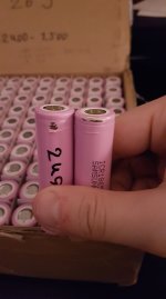
Just got myself 100Cells samsung 26J, tested at 2400-2500mah, most cells are in the range 2480-2500 thou, which is good.

9 of my cells have damages to the plastic covers, the question is do i dare to use them, or shall i replace the plastic cover?
161932470_911691272962934_1384429445997564299_n.jpg

this is the 2 most "damaged" covers. i will be using those plastic 18650 brackets to build my battery pack.

however i am going to use a 13S bms. so i am very lucky that just 9 out of my 100 cells where like this, at a 13S configuration i can fit 7 cells in paralell, and that gets me to 91 cells, and i got exactly 91 cells that are unharmed.

SO back to the question, what shall i do with this 9 cells? are they dangerous to use, or can i use them (perhaps in some other configuration, like a 3s3p or something)
 
MK2R said:
9 of my cells have damages to the plastic covers, the question is do i dare to use them, or shall i replace the plastic cover?
161932470_911691272962934_1384429445997564299_n.jpg

this is the 2 most "damaged" covers. i will be using those plastic 18650 brackets to build my battery pack.

however i am going to use a 13S bms. so i am very lucky that just 9 out of my 100 cells where like this, at a 13S configuration i can fit 7 cells in paralell, and that gets me to 91 cells, and i got exactly 91 cells that are unharmed.

SO back to the question, what shall i do with this 9 cells? are they dangerous to use, or can i use them (perhaps in some other configuration, like a 3s3p or something)
As long as it is just the wrap that's damaged, and it didnt' happen because of some other issue, and you are not going to have the wrap touching any other cells' wrap, then it doesn't matter if it's even present at all.

My question to the seller, if I were using those, is "what did they do to the cells while taking them out of the recycled packs they salvaged them from, to cause that damage?" As well as "what packs did they come from, and why were those packs being recycled?"

Just curious--did they provide you with the individual cell internal resistance measurements? Knowing those, along with the capacities, will help you build a balanced-capability pack, by making sure that on average each parallel group has the same capacity and the same internal resistance. That, in turn, will help your pack stay more close to balanced in use, at least until the cells age more than they are and change characteristics enough.
 
they damage to the wrap looks like something from physical damage during extracting the cells, no burns etc. I don't have measurements of resistance from the seller, just that the cells where tested at 1A current for discharge while measuring the mah.
my current multimeter is of budget design, it will not be able to measure that low resistance in ohms, the setting i can as lowest use is 200ohms it looks like. and i guess the internal resistance is in the miliohms right?
 
You can't use the ohms setting on a multimeter to measure a battery's internal resistance. ;) The ohms setting outputs a voltage, and so does the battery, and these will conflict (short version) and possibly damage your meter.

Internal resistance is usually determined as DCIR, which can be done by measuring the voltage drop at a specific current, for instance, and doing a bit of math with Ohm's Law (V=IR) to calculate what resistance would cause that much drop.

If you look at the cell-manufacturer's spec sheet (in this case, for the Samsung ICR1865???), it will probably say what current *they* tested them at, and what DCIR they got as an average, in their labs when characterizing that model cell. Since I cant' see the full marking on the cells, I cant' be certain what their model is, so you'll need to look up the spec sheet based on whatever is marked on them, if you want to do the test the same way they did.

There are also threads here on ES and elsewhere on how to do DCIR testing for single cells, if you want to poke around for those. Some of them are also about sorting cells for making a balanced-capability pack.
 
You just made me think about what we did in physics in school, this was over 10 years ago! i remember we did measure internal resistance in "old" alkaline cells. now i know how to check it, i just need to get a resistor of some sort to measure the voltage drop with a given resistans and 2 formulas to do the math.

I've seen some chargers in videos thou that can both test cells mah and measure the internal resistance too. perhaps i should invets in one of those chargers, even if they only can take a small amount of batteries at a time, i will need one... I "accidentally" bought 250 cells (5*50 at a 10S config with bmses), "old" E-bike batteries, but they are all untested cells so i need to test them, and it's gonna take time for sure...

Got any idea of what chargers-dischargers that measures the mah + internal resistance that are good?
 
did some calculations, if i am not doing it wrong ofc.

Cell: Samsung 18650 26J (2600mah new, max discharge 5.2A)

13S pack, max 50A (48V at 50A equals to 2400w, inverter max will be 3000w, however maximal use will be 2400w, this is the effect used to charge a prius phev at 8A 230V).

at 50A, each of the 13 cells will be draining 50/13 = 3,84A. and if i run a pack of 13S 7P each parelell of 7 cells will drain 3.84A, which is about 3,84/7 = 0.55A per cell. at a cell with 2400mah or more, it is around 0,2C of discharge

Am i thinking somewhat right here? 91cells in a total pack on a 13S BMS at 50A max.

And if i continue to extend the paralell, i will get lower and lower C value per cell?
 
Back
Top