Tab cooling prismatics.

Ianhill

1 MW
Joined
Sep 25, 2015
Messages
2,871
Exactly what it says on the tin tab cooling prismatics.

Whats the best method for simplicity but effectiveness.

Im thinking spot weld the tabs together then use an electrically isolating heat conducting pad so simular to what fets use that way i have a direct path from the internal foils.

water cooling over time can result in a conductive liquid if neglected and that would give an electical path between cells if there was no isolation between cooling block and tab so the thermal pad suits 2 purposes not only is it the heat transfer medium but the insulator too.

A thermal paste outperforms a pad but in this instance the pad is a good choice for the twin purpose and then off to a cooling radiator to take the heat away.

Does anyone have an input on this idea, i suppose tesla new cells would be the only cylindrical cell worth doing this too the 18650 and alike are the geared hub motor of the battery world case cooling or tab not really effective as a prisamatic tab cooled cell or the new 4680 cell.

I want to do this for a gokart idea i got the cells will be on the limit so need help or ill be lucky to get 150 cycles out if them but im going to design this clever so its not a big weight block on the side its going to be flat and in the floor pan 700×300×40mm in cell dimesion for a 21s 60ah pack then i got to apply a box and cooling
 
useless. the tabs cannot wick heat away from the other side of the cells so you are still killing them.

increase your number of cells, or get bigger ones and reduce the relative load so they dont heat up so much.

best solution: switch to a better suited chemistry.

you can fit a honeycomb shape into the 40mm hight (3 layers) and you can go 3 rows wide of 700mm long each. if you use high drain cells like samsung 25R for example you can pull quite a bit of power from a pack that big.

rough estimate: 324 cells would fit, prehaps a lot more if you finesse the case a bit in size.
your 21S lifepo4 pack indicates 70V max. so lets go with 17S regular lipo. 324/17 = 17S19P. the 25R can push 20A no problem so 19P x20A=380A@61V=23kW peak.

but without knowing more i think these numbers can be massaged more to fit the application.

best thing would be to increase the hight of the pack by 3cm so you can sit the cells upright. at that point you can fit a stupid amount of cells into that pack size. prehaps 600+ cells. at that point heating is simply a non issue so no cooling or special cells is required.
 
I will look for the reference, but "tab cooling" performed better than cooling the sides of the flat pouch cells.

Especially in high-amp cells that had multiple tabs per square-inch of anode/cathode.

I had always assumed that when packing flat pouch cells against each other, it would be good to insert an aluminum plate between them to draw the heat out from the centers.

It worked, but unfortunately it cooled the layers near the "skin", more than the layers at the core, leading to an uneven degradation of the active battery material. Once one part of the cell degrades, it leads to less capacity and premature voltage sag.

Tabs have a core that is either aluminum or copper, so they conduct heat well. If a pouch cell has the tabs from one cell that are skin-to-skin with the next cell, the clamps can be steel, since they don't need to conduct current.

But...if the tab-clamps are thick aluminum, they can also conduct heat away from the core of the cell.
 
Far from useless i see we rubbed up the wrong way i got to admire your love of the cylindrical cell but i can not afford to go that route 600 cells my bank balance just fainted.

Id thinking of using 21 lg 60ah li nmc cells that can deliever 240amp a cell but heating occurs nothing drastic but 20 mins of that build up would lead to a hot pack.

The reason i need to keep the size constraints is to keep the kart weight low and centred but from what ive researched its possible to get 2 qs 138 90h fitted to the rear axle so i may need 50kw or 2 packs one either side the kart, 21 cells 18kg ,25kg pack when enclosed so that coild be brought in around the 100kg mark fully built.
 
spinningmagnets said:
I will look for the reference, but "tab cooling" performed better than cooling the sides of the flat pouch cells.

Especially in high-amp cells that had multiple tabs per square-inch of anode/cathode.

I had always assumed that when packing flat pouch cells against each other, it would be good to insert an aluminum plate between them to draw the heat out from the centers.

It worked, but unfortunately it cooled the layers near the "skin", more than the layers at the core, leading to an uneven degradation of the active battery material. Once one part of the cell degrades, it leads to less capacity and premature voltage sag.

Tabs have a core that is either aluminum or copper, so they conduct heat well. If a pouch cell has the tabs from one cell that are skin-to-skin with the next cell, the clamps can be steel, since they don't need to conduct current.

But...if the tab-clamps are thick aluminum, they can also conduct heat away from the core of the cell.
Thank you magnets its your twin spar and qs motor brief i came across the rotors before that i thought qs was using standard extenal design, keep up the good work and good luck getting that hub monster thread sorted.
 
flippy said:
at that point you can fit a stupid amount of cells into that pack size.

Hey, you said it. But it depends on using a cell format that's a stupid choice for what you're trying to do.

If your objective is to use too many cells, why not 2032 format button cells? You can pack 20 of them into almost the same space as a single 18650.

If your objective isn't to use too many cells, then using 600 cells is a design failure.
 
Chalo said:
flippy said:
at that point you can fit a stupid amount of cells into that pack size.

Hey, you said it. But it depends on using a cell format that's a stupid choice for what you're trying to do.

If your objective is to use too many cells, why not 2032 format button cells? You can pack 20 of them into almost the same space as a single 18650.

If your objective isn't to use too many cells, then using 600 cells is a design failure.

Exactly that my friend, so many connection ive always been taught to design my system simple as possible and least connections as they introduce resistance fatigue and are the enemy.

The 600 cell plus would be a formidable opponent its possible to make but not practical glad im not the only one to see this.
 
you asked for advice to solve the cooling issue. i gave you 2 options that only need simple aircooling or much SIMPLER: no cooling at all.

dont start complaining about spot welding being difficult (it isnt) when you are looking for some A-Team style contraption to cool unsuitable cells for your appliction that physically cannot work.

how do you plan to compress your prismatics in 40mm? without compression you will not even manage a dozen runs.

is your go kart frame welded or bolted together?
 
flippy said:
you asked for advice to solve the cooling issue. i gave you 2 options that only need simple aircooling or much SIMPLER: no cooling at all.

dont start complaining about spot welding being difficult (it isnt) when you are looking for some A-Team style contraption to cool unsuitable cells for your appliction that physically cannot work.

how do you plan to compress your prismatics in 40mm? without compression you will not even manage a dozen runs.

is your go kart frame welded or bolted together?

I did say im spot welding the tabs so dont know where yout going by there im talking limiting the amount of connection's from 600 to 21.

I will compress the pack in a very clever arrangement my 40mm pack was mentioned as cell dimensions then theres an enclosure involved that will hold 21 cells 7 × 3 so ill only need 2 compresion plates the rest are the enclosure walls themselfs and i dont actual need to thermally bridge those plates if im tab cooling its like putting a cold can of coke on your forehead and feel it cool you vs putting it on your hair its still cold but the path is crap it takes a while to feel it.

Tab cooled cells form papers seem to be a vast improvement and im looking to implement not argue.

I appreciate your input flippy i do theres no bitter feelings and in time when the new 4680 cells reach yourself you will want to do this to and been less of them will make your day easier you got to admit, and if you could rid the world of nickel strip wouldn't it be a better place dont you think ? Tab dont suffer that issue half as bad but i wont rant against the 2 as 18650 has done me well in flashlights a 130 cell pack i got thats still working so i wont do them wrong but for this one i need cheap cells and big power so i got to go automotive wreckers route otherwise ill get no playtime at all.
 
the numer of welds being more prone to failliure is not a sound argument. while i fulyl agree that at face value it might appear so for the "untrained" observer. but from a engineering perspective its simply is false. its quite the opposite.

spot welding tabs is actually a worse solution from the engineering side. in relative terms those welds have to deal with a lot more issues then a "regular" strip welded 18650 pack.

while i do want to see bigger cells become the standard they are as of yet and for the forseeable future the lesser option. they are more expensive, you cannot buy them new with proper weldable surfaces and they are more difficult to conform into shapes to fit odd shaped stuff like bikes, scooters and go karts. and for the volume they can crank out considerably less power output due to the lower quality of these cells.

look, right now you are going up a hill trying to figure out how to cool down cells because they are getting too hot for the load they are under. that means either sacficing thickness to cool the cells over their surface with copper sheets or do tabbed cooling wich only cools the top bit and leaves the bottom to overheat with the usual "puffy" results.
adding a half-assed cooling setup is still a solution looking for a problem. you need to fix the problem so you dont need the solution on the fist place.
spot welding a couple hundred cells together is a LOT less work then physically welding, bolting and metalworking compression housings together and you still end up with a problematic setup that requires additiional cooling, hardware and many hours or tinkering to get it kinda working.

also, adding more capacity and cells in this manner will give you a considerable less amount of voltage sag, heat production and capacity.

spot welding a bunch of cells might be a "chore" for some people but its considerably less of a hassle then the alternative solutions that only half-work at best that you are endeavouring to do right now. from a time perspective i know for a fact that you can spot weld together a pack a considerable amount faster then you can build a tabbed-watercooled prsimatic battery with compresson housing. i am well on my patio sipping beers when you are still drilling and bolting a compression housing together...
 
Cheers slowco im going to be going back over that thread see what i can extract.

Jones likes the 5ah cell that has terminations same side whereas the lg is a crossover cell the tabs are either end so i think its better at heat wiking its more like the illustrations i read about in a paper whete tjey used peltier coolers on the tabs themselfs but tjey come with extreme low efficiencys so unuseable for my application but on the test bench they got a cell heavily abused it to tap out at 150cycles with 20% left so its just saging soon as any real load touches it vs a tab cooled identical cell that got 600 cycles to only 80% with the same load situation so its got some real testing to back it up before i even think of how to get something on paper thats safe reliable and does the job gets me close to 4c with little temp change and allows me to cool it in a small footprint.
 
Flippy i can not believe you have not bothered to even reserch tab cooling before you say it dont work

You other arguments are valid in their own way but your ignorance to the cooling path is beyond me and im not wasting time with pages of nonsense.

I will take on board your suggestions with tab welding and looking at using a punch method like those that came before me i dont want to rewrite something just finesse it a little

The cells are not going to be overheating as such but they will get warm when cycling so if i want a mess that can't compete reliably and hits power cut just like a tesla for example even the plaid cant shed its pack heat becuase the thermal path simply is not there thsts why they developed a complete new cell but your bashing on prismatics saying they are weak are you real have you seen any 350c 18650 i think not.

Serious if you want to learn something sub and watch but i won't slang with you thats enough i will be using a temp monitoring bms that will keep me from hurting anything but i dont wsnt them to even sweat if you get my drift longevity is key in racing no shit box won le"mans
 
i am not saying tab cooling does not work. i am saying it works poorly compared to the alternatives. especailly if reliabillity is you goal i dont see how active tab cooling is going to be the superior solution to your problem. tab cooling is a nice idea, but far from usable in the DIY field.

the big problem with tab cooling is simple: it does not cool the bottom of the cell wich casues a big temperature difference over the cells and that changes the IR inside the cell wich causes different parts of the cell to heat up more and the produce more power then other parts. its a mess from a reliablity standpoint and borderline stupid from a engeneering perspective considering now you also have to add active cooling, wich means pumps, radiators and heatsinks and dozens of connections and several layers of electrical insulation between the tabs and the heatsinks. in a car or truck where you have much less of a size, weight and volume restriction and have more control and space for the enviroment of the cells its fine as you can engineer the shit out of it, but not in a constracted application like a gokart.

also, tabbed cooling is hella expensive to build and takes a LOT of time. both things that you want to save on.

still, at least consider to just slap 1mm copper plates between each cell and fold those on the BACK side (so far away from the sparky bits) of the cells and cool the copper plates between each cell. combined with a compression housing and sufficient pressiure wich should already be present you can get better cooling performance then trying to cool the tabs and you dont have to worry about working on trying to cool eletrified bits. just removing the cooling from the sparky bits will greatly simplfy the cooling construction and the thicker copper plates will conduct heat better then the thin tabs.

ps: i am in the field of battery construction for nearly 10 years now. i know all about tabbed cooling and there are too many reasons to NOT use it compared to the alternatives.

please dont bring up tesla packs, they are not a valid comparison as they are not made for power delivery, they are made for capacity. a tesla model S pack filled with LG's HE4 cells or smasung 25R would deliver double or triple the current without killing the battery or needing to preheat it or even cool it. but it would have 35% less capacity.... the pwoer delivery would be comically big tho...
 
Basiclly theres conflicting data on tab cell cooling from basic observations theres has to be as theres differing chemistry cell layout shape construction methods so it is hit and miss to how good a result and even cooling you get.

I agree there could be benifit from adding a thin copper or alloy foil to the compresion plates to cool from all angles, what ill then have to watch is overcooling the pack thats why i wanted to go water cooling its much easier with a digital thermostat to open and close my loop to maintain a solid temp give or take a few fluctuating degrees.

By no means will i try and belittle you flippy i listening to what your saying i do not know it all i never will but i do think this can be pulled off and not with expensive exotics but basics and on the cheap, the key is to brainstorm it with yourselfs becuse its easy to fool yourself somethings grest when its not just ask stuff built here when the lock picking lawyer smashed his 2 unpickalble locks with a pick.
 
dont worry about belittering me. i am often the one that gets the short stick for trying to keep everyone on the ground. there are too many people think they are on the same level as professor level structural and electrical engineers.

you need simplifcation, you are not a car company that can trow millions at a building full of engineers. remember what the goal is here: you are building a high current battey made from a couple dozen plastic bags and want to slap it under a go-kart. (simplification but thats the gist)

the lowest hanging fruit you can simplfy here while keeping the same effect is simply to no bother with the angry side of the cell. let the angry side deal with the power and use a different side (preferably the widest one) and focus on that side for cooling. separate the cooling from the angry pixies. the utter worst case would be that your cooling solution (wich will probably contain water) gets mixed in with the angry pixies. i think we can all agree that event would be classified as "bad". especially if you are the one sitting on it.

cooling a cell on a worktop is not the same as taking a couple dozen cells with their heatsinks and trowing that on a gokart without suspention and trow it around a track a couple hundred times. you need proper engineerig to hold the tabs in place so the weight of the heatsinks is not pulling on them, otherwise you will internally short the cells causing a massive "bad" event just from the shocks.

the list goes on and on why putting heatsinks on tabs is a hell of a bad idea in this application. so please just park that idea and focus on methods that are actually feasable, practical and a LOT safer for a DIY solution. aka: copper plates between the cells. the copper would also add thermal mass and equalize the temperature better in the pack. without having to worry about electrical insulation you can make simple wquare copper blocks that the copper plates bolt to and the cooling water flows.
 
spinningmagnets said:
I had always assumed that when packing flat pouch cells against each other, it would be good to insert an aluminum plate between them to draw the heat out from the centers.

That is certainly the design of the Chevy Volt module...

It goes {(Poron foam) (Cell) (Aluminum coolant plate) (Cell) (Poron Foam)} and the (Repeat). One plate for every two cells, cooling one side each respectivly, at the certain flow rate, through the (volume) plate labyrinth to the other side ( return coolant line) .

Complex lattice of layers that need good compression to even close the module to the point of water tightness. THere are like literally 4 orings to compress every cell.... ( 96 orings for a 24 cell module.. that which there are some seven of in the car.. ) To provide the structure of the mod. I can imagine it being a nightmare trying to implement the OEM cooling system in a DIY hobby EV. I remove the cooling plates and orings and wash the coolant out cause I dont want cell rot.

I remove the cooling plates, orings, and reclamp the modules together for my uses.

Then I have a clamped, high power module, in its OEM case, in about less than a day... about the time it takes to spot weld up a pack.... and Im sipping coffee as the sun goes down. But much more capable than any cylindrical cell pack.

I have begun cutting the layers on my CNC machine into shapes I want for fun.. cause I no longer need alot of the modules (cooling parts) anymore. So I cut the cell case on the CNC, re-stack and re-assy. I can get the cell case to about within 0.1 of the cell.. make a "skin case" so to speak... that the cell fit in, almost as if, it was designed this way...

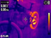
I have a ton of these plates if anyone wants some for experimentation. I dont use them, never even get a cell hot on a contin 2-3c discharge, levels I will never go over. They never get hot with high peaks either. Warm, maybe, warm compared to the ambient temp in the winter, but no noticeable battery heat on the FLIR record. Controller and motor get 2-3x hotter easily.
 

Attachments

  • bike2lgr.jpg
    bike2lgr.jpg
    22.7 KB · Views: 916
Flippy hold my bear watch this :lol:

Your over evaluating and complexing a situation it is possible its not a case of what can not be done its a case of whats required for the job and how we go about getting a result.

Ive never said im an automaker or a professor lol but im a trained mechanical/electrical engineer so to call me out say its not possible for people on my level is just fueling my fire to show you that it definitely is the principles are there and how you have spouted on shows you think your on the level of automotive pack maker yourself and can't even work put how heat works.

I'm not some pc nerd that got a water cooling loop fetish and just because an automaker does something don't mean its the best you seen car modifications by any chance ??? Ill fail to reply to you now your just ruining a thread.
 
That's good to hear dogstick as 4c max wont be to far from where your at and theres little heat no melt down or swollen cells check that flippy, im not going to use 1 single o ring or put water :| through complex network of plates.

Thermal pad either side of the cell tabs were 2 meet for a connection and waterblock clamped to both sidesthe fluid only flows round the tab area then thin foils can connect the cell surfaces to the retaining box.

I see jones use a non conductive box to keep things safe as possible and theres no reason why i could implement simular but have a water loop both tap sides and maube connect to the foils in a simular way or use a heatsink and solid state cool them but there will be a lack of control then on cool and warm days keeping the happy c rate from sagging to cold or life span to hot.

Plus liquid one and air the other with create a temp differential across the cell i need to keep it even so planning to water cool the foils if they are even required at all as tab cooling is more effective to begin with and i wont be stacking a thick sandwich of cells heat will be able to move all directions fast and even.
 
I think personally, we need to talk about how many WATTS ( wasted heat, watts, BTU, ect.) per AMP HOUR ( unitized capacity that takes volume of the pack into account) need be shed. Put some units in there.

Not just how to do it. but the actual ( numbas). When you would actually need it. How large of a pack, how dense. Or small, or less than dense, (< density?). What makes the necessity for a cooling regime to be implemented.

How much, or many, ( watts of waste heat), you must create, to make the heat that is detrimential, then how to ( shed) transfer a ( burden) of heat away from the cell in practice.... ( heat load) ( cooling system sizing).
 
DogDipstick said:
I think personally, we need to talk about how many WATTS ( wasted heat, watts, BTU, ect.) per AMP HOUR ( unitized capacity that takes volume of the pack into account) need be shed. Put some units in there.

Not just how to do it. but the actual ( numbas). When you would actually need it. How large of a pack, how dense. Or small, or less than dense, (< density?). What makes the necessity for a cooling regime to be implemented.

How much, or many, ( watts of waste heat), you must create, to make the heat that is detrimential, then how to ( shed) transfer a ( burden) of heat away from the cell in practice.... ( heat load) ( cooling system sizing).

Ive been looking at the rate of heat flow formula so i can estimate the maximum flow from the tabs surface area.

But one things for sure its not alot unless the cell is genuinely been pushed to far and i dont want to do that this is not for that purpose we are not overclocking here, a small peltier managed to remove the heat its more if a constant build up over time full pack discharge may feel warm but over the period of discharge its not alot per second barely a few watts of loss per cell so the radiator would not need more than 120×240 setup to remove the whole carts heat.

I wont need anywhere near ice levels of radiator cooling but there will need to be a rad of some sort enough to equal the 21 peltiers work thats in the 200watt actual work done range as they are not efficient that assuming they were 100w models and they could of been as little as 10w in the same size package.

Way i see it is if i overshoot the requirements then its not going to perform no worse but if i undershoot its useless exercise.
 
a peltier is only 5% efficient. so good luck with that :lol:

you need 4kW of input power and heat dissipation to get 200W of cooling.
 
flippy said:
a peltier is only 5% efficient. so good luck with that :lol:

you need 4kW of input power and heat dissipation to get 200W of cooling.

You really dont read my comments as i said i wont he using the peltier it was for lab purpose to keep a steady state i dont wear a white jacket or do i pretend I'm special.

Thank you for the good luck but i dont need it ive got knowledge my friend and a plan.
 
Ianhill said:
Thank you for the good luck but i dont need it ive got knowledge my friend and a plan.
Keep telling yourself that.

:bigthumb:
 
Don't try and limit others by your own ability i was fair to you but you keep been condescending of my ability and knowledge so watch on as i put a test rig together and start getting some useful data from cool cells not your hot air.

I will be sure to test for capacitive leakage and get some useful data on building the bigger version ill use a 4s 10ah pack ive got 2 spare so ill run a none cooled test high c rate vs cooled and get some actual pictures data and bit more belief it can be done its not a case of flooding the cell area but more of a touch in the right spot tickle the cells g spot and extract its kw amps love heat.
 
Back
Top