Designing a Bidirectional dc dc converter

ankanphukan

10 mW
Joined
Oct 1, 2021
Messages
32
Hello everyone,

I need your help!!

I am designing a bidirectional dc dc converter. I am following the traditional bidirectional converter circuit with capacitors, inductor and MOSFETS. But I am facing a problem in that design.

As we all know, in the boost mode, one of the two mosfets acts like a diode; while the other mosfet behaves like a switch. Likewise, in the buck mode operation, exactly the opposite happens.

I tried to design and construct the boost converter and buck converter separately; i.e. I used one mosfet and one diode to realize both the converters separately. Both my designed converters are working perfectly fine, with an excellent efficiency.

Here, comes the main problem. As mentioned earlier, I want to design a bidirectional dc dc converter; i.e. both the boost converter and the buck converter must be in the same circuit. For this, I have to use two mosfets. But, whenever I connect both the mosfets as per circuit diagram, the converter doesn't work. It seems there is a tremendous voltage drop somewhere in the circuit.

Could anyone kindly help me solve this issue. I would be very grateful.

Kindly take out some time and help me out.

Thank you.
 
You must post the design and schematic of what you are doing, along with the measurements of the problem noting where you see this problem, for us to help you figure out what the problem is.

If you won't do that, we can't help you fix it.


We also can't help if you won't reply to us.

In your threads so far, people asked you questions that you don't answer, and you stopped replying to the threads, so we can't help you further with those questions. If you want the help, you have to answer the questions.
 
ankanphukan said:
As we all know, in the boost mode, one of the two mosfets acts like a diode; while the other mosfet behaves like a switch. Likewise, in the buck mode operation, exactly the opposite happens.
Sort of. In a bidirectional converter of any reasonable power level you have to think of both top and bottom switches as switches and not diodes; you will be controlling them explicitly, not just leaving them on or off.
 
fechter said:
Can you post a schematic?

I apologize for the late response.

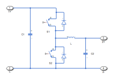
I am using the conventional half bridge bidirectional dc dc converter topology. The schematic is attached below.
bidirectional_dc_dc_converter_non_isolated_eq_circ.png

The S1 and S2 are power mosfets.

Please help me out.
 
amberwolf said:
You must post the design and schematic of what you are doing, along with the measurements of the problem noting where you see this problem, for us to help you figure out what the problem is.

If you won't do that, we can't help you fix it.


We also can't help if you won't reply to us.

In your threads so far, people asked you questions that you don't answer, and you stopped replying to the threads, so we can't help you further with those questions. If you want the help, you have to answer the questions.


I apologize for my late response.

I have attached the schematics. Please help me out.

The converters are working perfectly fine separately. i.e., when I manually change the gate signals of the two mosfets, the converter is working as a buck and boost mode perfectly fine. But I want the switching to be done automatically.

What I mean to do is, based on the direction of power flow, the converter should work in both direction automatically.

Please take out some time to help me out.

Thank you for your time.
 
That's just a basic diagram of how it operates; it's not the way you'd actually build it; it doesn't include all the parts, or all the wiring.

What we need to help you is the actual schematic of the specific parts you are using, wired exactly the way you wired them.

Without that, we can't know what you've connected where, and without knowing that, we can't know why it is not working as desired.
 
JackFlorey said:
ankanphukan said:
As we all know, in the boost mode, one of the two mosfets acts like a diode; while the other mosfet behaves like a switch. Likewise, in the buck mode operation, exactly the opposite happens.
Sort of. In a bidirectional converter of any reasonable power level you have to think of both top and bottom switches as switches and not diodes; you will be controlling them explicitly, not just leaving them on or off.

Thank you for your response.

I want the switches to work automatically based on the direction of power flow. Till now, I was connecting the switching pulses to the mosfets manually.

Please take out some time to help me out.

Thank you for your time.
 
ankanphukan said:
I want the switches to work automatically based on the direction of power flow. Till now, I was connecting the switching pulses to the mosfets manually.
You can _sort_of_ do that.

You have two choices there. One, you can do a fixed-ratio converter, where there is no feedback. Vicor makes these. You set up a converter that operates at a fixed ratio (say, 4:1) and then if you put 12V on the low side, 48V appears on the high side. It operates like a "DC transformer" and the currents/voltages on either side determine what direction power flows.

However, there is no regulation whatsoever.

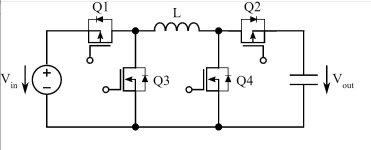
The second is a regulated converter, with a standard 4-switch buck/boost configuration (shown below) and a control IC.

buck_boost.JPG

This will buck and/or boost, but needs a control to tell the system what direction to drive power. The system will then regulate the output voltage to the setpoint, and draw as much/as little power as it needs to accomplish that. This is more common.
 
Back
Top