Project

pkirkll

100 W
Joined
Sep 6, 2012
Messages
230
Location
ak- AND PARTS UNKNOWN
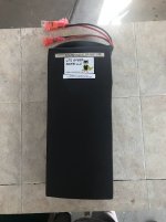
I have a battery that has been in the box since 6/2020----- 1 year and 10 months!

I know I will get torn up over that,, but remember what was going on that whole time.

The question is: since i am assuming the if BMS put it to sleep a while back... would that save the cells or would it still self discharge until flat?

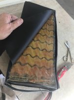
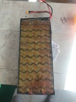
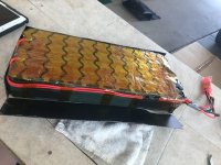
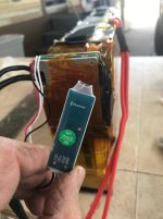
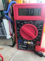
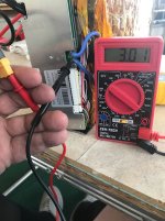
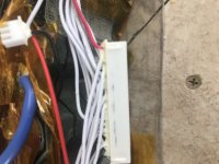
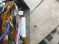
I get no voltage off the main lead. I haven't unwrapped it to see the BMS

It is shrink wrapped nicely and may have a Xiaoxiang Bluetooth Battery Management System, it is a :

20s10p 72v32ah using Panasonic BD 18650 cells (3200mah 10 amp)-- 60 amp continuous BT BMS -- 16x 7 x 3"

Woe as me-- I fear I have turned it into a brick ---piss poor maintenance.

Next step????

Do I dare hook it to the charger???--- I saw a bike burn once from a puffy cell being overcharged

Thanks in advance

paul
 
What are you waiting for? Remove the wrap, disconnect BMS. Check each of the twenty parallel groups to see if all are completely drained (zero voltage). You could try charging each parallel group one at a time at 2.0A for 3 min using a 6S RC charger set at 1S.

Makeup your own cable using Deans connector to RC charger neg/pos Deans connection and aligator clips on the other end of your own cable to battery p-group (e.g. B-toB1, B1toB2 ... B21toB+). Check to see how long (if at all) each parallel group holds that 3 minute minimal charge.

See how many (if any) of the p-groups will still take a charge or maybe the RC Charger won't allow a charge. You could try charging at 0.50A for 10 min on each parallel group and see how long they hold the minimal charge.

Chances are better than 50/50 that you won't be able to regenerate the twenty parallel groups if they were completely drained by a faulty BMS.
 
All good advice above.

That bring said, when you think you are ready to test, charge the battery where it would be no problem if it caught on fire.

Then ride around the blick so that if the discharge causes an issue you are not far from home.

Id say after three charge/discharge cycles, you will know that it is relatively safe, and what the current range is...
 
No voltage at the discharge port may just mean the BMS has turned off the output because the cells are low.

Do you read voltage at the charge port?

If not, then it's likely that has also been turned off, meaning the cells have discharged enough to either cause the BMS to turn it off to prevent a fire from overdischarged cells.

It could also mean all the cells are completely discharged.


If you read a normal but low voltage (above LVC) at the discharge port, and you trust the BMS, then you can connect the charger; the BMS has not found any cells too far discharged to be safe to recharge. (If the BMS is wrong, having it outside away from all structures during this process is probably a good idea)

If you don't trust the BMS (often a good idea in these cases), you can open it up and measure at the BMS balance connector between every wire pair, and post the list of voltages, starting from the most negative cell and working your way up to the most positive. You should have the same number of readings as you do series cell groups (20, in your case).


If the cells are actually zero, or even below the cell-manufacturer-spec-sheet minimum charge voltage, I would not recommend recharging them, as there will be a risk of internal damage that could result in catastrophic failure at any point in the future (during charge, discharge, or just sitting there), and you cannot know if this has occured or not.

Even if they are not damaged in a way that could cause catastrophic failure, they'll never be the same as they were before this happened.
 
Thanks everyone-- i guess I will check the voltage on the battery side of the BMS first.
I suppose the BMS has to have some power to be able to send out info on bluetooth.

Im down in the desert of AZ but it pretty windy right now dont want to start a big fire so i wont try to charge it right away until i can see what the cells are doing individually...

i have an innate feat of shorting batteries when im testing--- im not proficient in it at all

i paid about 1100.00 for it and the charger--- but i may well be better off to scrap it vs burning down my park model camper in the over 55 park i am at now---- definitely not a good place to charge it....

Any thoughts are welcomed--
i have been on here in the past, just recently got settled for a bit and am working on a couple of different projects--- like a 9Continent 9C30H88 rear hub GS trike, Schwinn Shuffle rear hub, Swagtron mini ..36v 4ah
 
pkirkll said:
... i wont try to charge it right away until i can see what the cells are doing individually...
The best you can do is test the condition (voltage variance) of each 10P group and not each individual cell within each p-group.
pkirkll said:
i have an innate feat of shorting batteries when im testing--- im not proficient in it at all
No need to fear when just checking the parallel group voltages (if any voltage) with your DMM. Determining the degree of voltage variance among the 20S 10P groups will give you some idea of the condition of your battery. Hopefully, no more than 0.10V variance between all 20S 10P groups.

If some of the twenty 10P groups have more than 0.20V variance it's not possible to regenerate your battery (IMO).
 
There's not much fire risk for charging to less than full. I would put it on the charger for 30 min and see if the output starts showing anything. You can see if the bluetooth app starts working too.
 
Here are some pictures-- i will have to watch some more video to get the hang of test parallel groups.

I did get 3.0v from the B- on BMS and the red wire on charging XT60.
No voltage on the B- and red discharge wire XT90.
Going to have to watch some more videos to see how to pin the parallel group properly.
 

Attachments

  • 1-.jpg
    1-.jpg
    56.6 KB · Views: 504
  • 2-.jpg
    2-.jpg
    69.2 KB · Views: 504
  • 3-.jpg
    3-.jpg
    55.8 KB · Views: 504
  • 4-.jpg
    4-.jpg
    112.7 KB · Views: 504
  • 6-.jpg
    6-.jpg
    54.3 KB · Views: 504
  • 7-.jpg
    7-.jpg
    79.1 KB · Views: 504
  • 9-.jpg
    9-.jpg
    87.4 KB · Views: 504
  • 5-.jpg
    5-.jpg
    67.8 KB · Views: 504
I understand why i dont need to check each individual cell now---- one p group could be bad and from what i have read here--if that is the case then the whole group should be canned.

thx
 
Yikes — it looks like you have correctly placed your multimeter probes on B- and pack positive, and are still reading 3V. That, to me, would indicate that the pack is rather dead and in a condition I would not try to recharge.

If you wanted to dive deeper and double check individual parallel group voltages, you can unplug your balance leads (big white plug on the BMS) and check. Testing neighboring pins will give you the voltage of a single cell group. Careful with your probe tips while doing this, as the pins are small and close together.
 
The low reading most likely indicates the BMS is tripped and the actual pack voltage is probably much higher.

I would use a sharp needle tip probe and poke through the Kapton tape on the cell connections to measure the voltage of the cell groups. If you have easy access to the BMS connector, you can measure there using a pair of solid strand wires:

Single Cell Charging Hookup 2.jpg
 
i wish i knew where to put the MM probes to test each p group---

at first look it seems they are all hooked together ---do i have to pin each side of the battery at the same time to get a positive and neg pf each p group??

When i finally understand how to test a p group i will be very happy--- i have to up my game to be playing with these things

Once again i wonder about charging it like an above post said for 10 minutes and see if the BMS turns the Bluetooth on so i can read cells that way

but I'm going to figure out how to test it by pinning the BMS plug JST ?----- or figuring out how to pin each parallel group

Are these the p-groups Inked4- (1_LI.jpg
 
pkirkll said:
i wish i knew where to put the MM probes to test each p group---

at first look it seems they are all hooked together ---do i have to pin each side of the battery at the same time to get a positive and neg pf each p group??
That is one way.

Or start with one meter lead on the metal strip of an "end row" of the battery, where one of the main thick red or black wires already goes to. Then the other meter lead on the metal strip on the other end of that same row. write down reading.

move meter lead from end row to next row's metal strip on the same side, write down reading.

move meter lead from other side's row to next row's metal strip on that same side, write down reading. repeat till you run out of rows.


Or just test at the BMS connector.

One meter lead on the end wire of the connector. other meter lead on the next wire over. write down reading.

Move meter lead that was on the end wire to the next next wire over. write down reading. Repeat until you run out of wires.


Post all the readings here, whichever way you get them.


Once again i wonder about charging it like an above post said for 10 minutes and see if the BMS turns the Bluetooth on so i can read cells that way
I'd test the voltage of the groups first. It is less risky, since you already have the pack open.
 
OK thanks

here is a picture of the BMS connector--
Im also making a schematic/diagram up so i can visually see where to pin

tried pinning the JST plug but i dont have anything that small---

If you can tell me --- Like 'black lead on 15A while red on 10B".... That i can follow--- and once again i apologize for my lack of knowledge--just trying to flatten the curve again-

Honestly, I pinned it everyway i thought i could and only had a few 3.1's-- `
 

Attachments

  • SCHEME.jpg
    SCHEME.jpg
    1.8 MB · Views: 444
  • JST +.jpg
    JST +.jpg
    1.5 MB · Views: 444
  • JST.jpg
    JST.jpg
    1.5 MB · Views: 444
I don't understand the diagram. You have two horizontal rows, and two vertical. I've never seen a BMS connector made like that, and yours does not appear to be made that way either.

The BMS connector should only have one row of pins.

You start at one end, and go across to the other, in pairs, moving only one meter lead at a time.

You don't show the other side of the connector, but many of them have some of the metal of the contacts showing thru the plastic, and you can touch your meter leads there.

If they do not, you can use thin needles, straight-pins, solid-strand wires, etc., to stick into the actual holes on the connector, then touch your meter leads to those to measure.
 
OK.!!!! i turned the JST over an SURE enough there were metal access points..

I just put the red MM lead on the red lead of the JST and then i put the black MMlead on every pin to the left....

I dont think this was the correct way
 

Attachments

  • cells.jpg
    cells.jpg
    793.8 KB · Views: 429
It's not the way I described, but it still got you voltage readings.

To get the individual cell readings, you subtract each reading from the one below it in the list, to get the cell reading for that "below" one. (each cell group voltage is the difference between it and the next one, when measured the way you did it)

What it comes down to is that all the cell groups are discahrged down to effectively zero (maybe a tenth of a volt or two each).

I wouldn't try to recharge those. :(
 
Yeah it looked pretty bleak----

Thanks for your help

We got the question answered now to move on to the next project.

Oh and what is the proper way to dispose of this unit,

paul
 
Those numbers look very low! It's hard to believe the cells were drained that low. If these are the actual voltages, then the pack is pretty much toast.

My experience is the tips on my voltmeter are just a little too fat to make contact with the little metal tabs on the JST connectors. You may have been getting a false reading if you fingers were touching the probe tips.

To measure directly to the pack interconnect strips, you put one probe on one side and the other probe on the back side to measure across each cell bank. You need to poke through the tape or remove a section first to make contact. I would try double checking to make sure these are real readings.
 
Back
Top