Can I shorten external shunt wire?

caleb7

1 W
Joined
Sep 23, 2020
Messages
50
Location
İstanbul
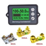
Would it be OK to shorten the "shielded wire" of TK15 Wattmeter (https://www.aliexpress.com/item/32703947698.html)? The cable is 1 meter and currently it's folded between other handlebar wires.

The cable between shunt and the display unit is somehow damaged inside (one wire is not conducting) and I need to get rid of the damaged part. I suppose noise protection is important but I'm not sure if shortening it will affect accuracy. I can shorten the wire and crimp new JST pins, without introducing newly exposed parts. Although I don't have that yellow colored pins, just the usual ones.

Here they sell different lengths of this cable, but they also say "don't cut it" - that doesn't make so much sense. The English they use in that page isn't very clear to me.

https://www.aliexpress.com/item/1005003740034677.html
 
I think I've found some useful information about it in the online manual. It says about different sized wires, and says use shielded wire if it's longer than 50cm (screenshot from PDF manual is attached below).

I read the paper manual before but I either skipped/forgotten this part, or online version is a bit different.

So I think it should be more than OK if I shorten this shielded wire to about 50cm.

Screenshot_20221207-202034_Samsung Notes.jpg
 
Can you please send a actual photo of shunt resistor board? Does the board contain any IC ?
 
Can you please send a actual photo of shunt resistor board? Does the board contain any IC ?
What shunt resistor / sensor board, in what device?

I ask because you've posted this question in multiple unrelated threads. (this is the other one
Coulometer blues )


And what device do *you* have, and what are you needing to do with it?

I ask this because it will help us help you figure out whatever it is you need to know / do to use your device as you need to use it.
 
Can you please send a actual photo of shunt resistor board? Does the board contain any IC ?

Thanks for the replies.

It doesn't look like the shunt board has any integrated circuit, see the photo below. I have the 100A version. I shortened by re crimping new pins to cable. I cannot verify if it affected measurements. The watt values look like as before, or a few watts higher than usual at ~250W load? But if resistance dropped because of the cable, the value I think would go lower(?). By the way, it originally had "gold" colored pins, I crimped usual "silver" looking ones on one side of the cable.
 

Attachments

  • 80V-50A-100A-350A-TK15-profesyonel-hassas-pil-kapasitesi-test-cihaz-i-in-ta-nabilir-ekipman.jp...jpg
    80V-50A-100A-350A-TK15-profesyonel-hassas-pil-kapasitesi-test-cihaz-i-in-ta-nabilir-ekipman.jp...jpg
    106.1 KB · Views: 6
What shunt resistor / sensor board, in what device?

I ask because you've posted this question in multiple unrelated threads. (this is the other one
Coulometer blues )


And what device do *you* have, and what are you needing to do with it?

I ask this because it will help us help you figure out whatever it is you need to know / do to use your device as you need to use it.
I am asking about the shunt resistor/sensor board used for TK15 Coulometer. The reason, I am finding it difficult to buy the TK15 unit more of you can say it's turning out to be very expensive to get it to India. If the sensor board doesn't have a chip on it then it means that just the voltage drop across the shunt resistor in the sensor board is sent to the main unit in analog form. If so than using long wire will effect the reading. If a chip is present on the board, possibly the analog voltage is converted to digital signal so length doesn't matters. If length does have an effect then better for me is to opt for a cheaper and easily available PZEM-015 battery monitor. The length of the wire between the shunt and the meter would be quite long for me.
 
Last edited:
Thanks for the replies.

It doesn't look like the shunt board has any integrated circuit, see the photo below. I have the 100A version. I shortened by re crimping new pins to cable. I cannot verify if it affected measurements. The watt values look like as before, or a few watts higher than usual at ~250W load? But if resistance dropped because of the cable, the value I think would go lower(?). By the way, it originally had "gold" colored pins, I crimped usual "silver" looking ones on one side of the cable.
This is a picture from the internet not of the actual product so determining if a chip is present or not is impossible.
If there is a chip on the shunt resistor/ sensor board than possibly the analog voltage, voltage drop across the shunt resistor, is converted to digital signal so length of the wire would make no difference.
If analog sensing is used than increasing the Solength of the sensor board cable will increase the series resistance of the wire resulting in voltage drop across the cable and giving a reading less than actual and vice versa for reducing the length of the cable.
The manufacturer provides a longer length cable. It could have thicker wires in it to compensate for the length. Shielded cable is used to prevent interference from RF signals.
For a shunt of 100A /75mV, the current per mV is 100/75= 1.33 Amps. So if you add series resistance by increasing the length or reduce the series resistance by decreasing the length of the cable. You could get an error reading of 1.33 Amps per millivolt.
Gold plated pins have a better corrosion prevention than silver pins.
 
This is a picture from the internet not of the actual product so determining if a chip is present or not is impossible.

Thank you for the information.

I'd want to inspect it but I cannot easily reach the shunt on the bike, even if I did I wrapped it with some tape. But I think it looks just like in the photo. I don't know if they hid an IC under the board.

Check out the attached photo from the manual. It says when the backlight stays on, RS+ and RS- are connected reverse so the meter thinks it's discharging when charging. Maybe it suggests these pins are right from the shunt's poles, and not from any IC.

TK 15 pins.png
--

TK 15 pins 2.png
 
Based on that diagram, there's no electronics in the shunt, it's just a resistance. (same as the Cycle Analyst could use).
 
Thank you for the information.

I'd want to inspect it but I cannot easily reach the shunt on the bike, even if I did I wrapped it with some tape. But I think it looks just like in the photo. I don't know if they hid an IC under the board.

Check out the attached photo from the manual. It says when the backlight stays on, RS+ and RS- are connected reverse so the meter thinks it's discharging when charging. Maybe it suggests these pins are right from the shunt's poles, and not from any IC.

View attachment 332186
--

View attachment 332187
Just going by the diagram the shunt shows 4 wires indicating that it is not a plain resistor but integrated chip with the shunt. For higher current sensor boards it may have a separate chip on it. Thanks for the info but I will still search for actual photo of the shunt resistor/ sensor board to be 100 % sure.
 
It's like any other shunt, just in a box. Here's what I use. The P- and P+ would be the posts for the big connectors on the negative battery cable. The smaller phillips screws are for the smaller RS+ and RS- sense wires. The meter uses the RS+ and RS- sense wires to impute current, and uses the B+ and B- for voltage. Then combines the two to impute power or watts.

61Gdx7HjN+L._AC_SL1500_.jpg
This shunt is used with which device? Please provide model number.
 
Back
Top