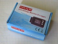
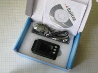
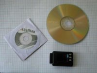
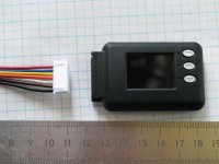
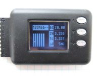
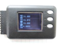
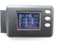
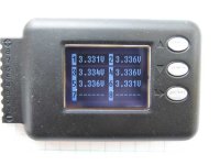
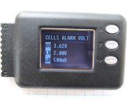
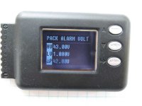
CellLog 8S battery monitor and logger - any reviews?

tailwind

100 W
Joined
Apr 3, 2007
Messages
136
Location
Melbourne,Victoria, Australia
Great little device for monitoring cells.

Features include,

Bar graph display,
0.001V display,
Various configable alarms, including cell low voltage alarm,
Alarm port ( cutout for throttle or controller?),
and can log voltages for each cell.

http://www.hillrc.com/EnProductShow.asp?ID=96

200952303512426.jpg


User manual,
http://www.hillrc.com/UploadFiles/CellLog_8S.pdf

Discussion here,
http://www.rcgroups.com/forums/showthread.php?t=1055820

I have purchased one to try it out but I see that Julez is ahead of me.

Greg
 
Start up screens and tone.
What I have done here is disconnect the black lead , pin 1, from the pack and reconnect.
It should be possible to put a switch on the pin 1 lead and use it as a on/off switch.
I have got no way of measuring any current it might be drawing from the pack when off.

[youtube]1n-raHqIUrw[/youtube]

Example of the error tone and bar graph display.
I put a pot on one of the leads. This triggered the >500mV cell difference alarm.

[youtube]uJMwxVBBlOM[/youtube]

Greg
 
For 8 cells, it would have to be a 9 pin connector, not a 7 pin but it looks like you can fit in a 7 pin connector. If so, you should be able to monitor any 2s through 8s battery.
 
Thanks for the review!!!

I just bought 2 of them.

I would ove to start a group that wold buy aom 24s model if celllog would like to fabricate them!

or to make slave and master units!

Doc
 
Seems to me that multiple 8S units could be stacked for 24S monitoring.
Just NEVER try to download any data from them while they're stacked!

Or, if they must remain stacked, use digital isolators on the USB lines and (if necessary) an isolated 5V supply for the USB power lines. There are some digital isolators that provide isolated power too, from Texas Instruments IIRC.

DISCLAIMER: The above ideas are preposterous and should never, ever be attempted by anyone!
Our planet, and most likely our entire galaxy, will be instantly vaporized if you do.
 
CamLight said:
DISCLAIMER: The above ideas are preposterous and should never, ever be attempted by anyone!
Our planet, and most likely our entire galaxy, will be instantly vaporized if you do.

:mrgreen: !!

This cellLog technology is so advanced than it seems to contain some black holes!!

no joke... stacking many of them seems interesting if paying attention to common ground problem thru the 0-5V but having a ALL IN ONE would be nice!.. I can already imagine how the EV community would be so interested to a cheap cell monitoring and datalogin device!!.. maybe making up to 40s device with display( for the EV UP TO 144V)... let say the price could be.... 140$

and with the alarms ext trigger connected to the ebrake line that would make that device a real LVC part of a complete BMS.

Doc
Doc
 
nutsandvolts said:
Anyone know the pricing on these monitors? No pricing on their website. I am guessing they are quite expensive.


ON SALE 28$!!
hobbycity

Doc
 
tailwind said:
Start up screens and tone.
What I have done here is disconnect the black lead , pin 1, from the pack and reconnect.
It should be possible to put a switch on the pin 1 lead and use it as a on/off switch.
I have got no way of measuring any current it might be drawing from the pack when off.

[youtube]1n-raHqIUrw[/youtube]

The current is minimal - a DVM between gnd and pack gnd will reveal power levels consumed at various screen brightness... if you use a 3pst you can connect GND from each pack (or parallel of packs) and then toggle the switch on and off connect / disconnect the CellLog8 - this could also be fully automated. I will explain this later in more detailed instruction. The current drawn with the gnd pin interrupted is 0 a
Ideally... these would come on and off with the main ignition system so they were only in use and powered when the bike is being used... additionally they should come on when charger port is energized (still need a precharge resistor for these meanwells too.)

tailwind said:
Example of the error tone and bar graph display.
I put a pot on one of the leads. This triggered the >500mV cell difference alarm.

[youtube]uJMwxVBBlOM[/youtube]

Greg
 
Post by Doctorbass » Sun Sep 20, 2009 12:31 am
Thanks for the review!!!

I just bought 2 of them.

I would ove to start a group that wold buy aom 24s model if celllog would like to fabricate them!

I'm in, love to see one of these for 20 -24cells
 
This can really save me the pain of logging manually with a multimeter, paper & pen... which I gave up on last year btw *chuckles*

I promised my self not to get teeny weeny meters like this because what I REALLY want are large ass needle gauges on a netbook
View attachment Picture 8.png
so I was willing to just wait till plug & play gear is available. But this thing has USB so I wonder if the meters will show on a netbook while riding

My packs are 15s, will I be able to use one for the first 8 cells and another for last 7 cells? Is this what's called "stacking"?

Is this battery operated? Or powered by your bike's pack?

J+
 
The CellLog is powered by the pack being monitored. It has been reported however that the power is is not shared equally by all of the balance leads which can lead to a cell inbalance if left connected for long durations between chargings. Junsi has recommended a specific modification remedy for those who it may affect. Here is an informative thread about the CellLog from the RCG forum:

http://www.rcgroups.com/forums/showthread.php?t=1055820
 
mwkeefer said:
if you use a 3pst you can connect GND from each pack (or parallel of packs) and then toggle the switch on and off connect / disconnect the CellLog8 - this could also be fully automated. I will explain this later in more detailed instruction. The current drawn with the gnd pin interrupted is 0 a
Ideally... these would come on and off with the main ignition system so they were only in use and powered when the bike is being used...

Please show us how you wire these things together so they are powered only when we power-up our bikes.

I'm definately getting 3 of these things, who needs a BMS if we can monitor daily activity, plus a good charger.
 
I'm sure if we all made a group order we could get these specially made for 12- 24 cells.
 
momo said:
I'm sure if we all made a group order we could get these specially made for 12- 24 cells.

Count me in, i want three atleast.
 
I would buy one and know LOTS of people who would also want one, has anyone contacted the company that produces them to see if they would be interested in building the?
 
Wired mine and made an abs case, I will still have to make an acrylic clear cover to make it water-resistant. I then mounted them to the case using 3M Dual Lock tape. The 3M also acts as a shock dampener to the CellLogs. Also shown is the miniature 3pdt switch mounted at the bottom of the case for on/off operation. I coated the contacts with several coatings of liquid electrical tape, hopefully this protects it from the elements.

I've done about 80 miles riding with the CellLogs and it seems to be performing as it should. I tested the built-in alarm sound and its loud enough to be heard when riding. I might use an external piezo-buzzer when the clear cover is mounted in case the sound is muted. I haven't done any data logging and pc connectivity yet, which I'll eventually do in the future. As recumbent has mentioned, this replaces an onboard bms to monitor low voltage. I'm thinking of just using an external "Even newer" bms with a 1A shunt for balancing while charging since my MKS 3-in-1 have been boringly slow to balance.
 

Attachments

  • Copy of HPIM0752.jpg
    131.7 KB · Views: 4,443
Wow!

Nice setup on the CellLog8 units.

I am currently working on interfacing a single MCU (Atmega168 or 48 will work fine) to these CellLog8 before the USB chip... this is TTL level serial IO before the USB chip.

The idea is to allow a single processor to watch all 3 units and provide a single consolidated UI and slightly better / more adjustable alarm methods... for instance when charging, only HVC alarm should be monitored not LVC... I want to manage these from the primary MCU via single digital output coupled to optos then used as a virtual switch to do a form of "SendKeys" remote control to the units.

My intent is to use them for not only LVC but also for charge monitoring at cell level along with a simple (I call it simple, it's not turning out to be simple) current drain / shunt which for instance:

As highest cells reach 4.159 and there are still cells < 4.150 then... I will stop the bulk charge, engage a drain via balance taps on the cells > 4.150 until they =< 4.150 and then resume charging process at lower current limit until all cells are balanced. I don't know what this form of charging is called but my iCHarger worked this way (I've looked at hundreds of charging session logs) as soon as the cells past the 4v point which could slow down charging considerably but I guess it's better to bleed off .009v throughout the charge than to charge till the first cell hits 4.15 and then drag all cells down to the same level. It seems that since we know shorter discharges of lower C will lengthen the battery cycle life, this may be the optimal way to charge... I think the ULTIMATE charging method is shunting the current around a cell which is full because then there is no bleeding of any kind and as such, each cell sees a single charge cycle for each pack charge cycle. That said, it's easier (for me) to monitor and turn the charge on/off while engaging cell level discharge.

Hope this helps !

-Mike

PS: Yes... I will post when I have everything in a state that it can be seen without a rats nest of wiring (reminds me of some of my first programming code from 20+ years ago, spaghetti)
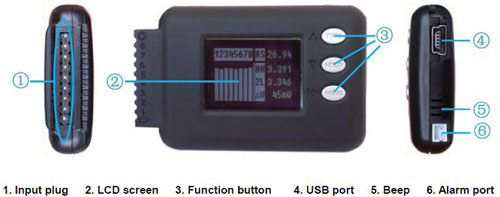
 
Can the backlight be forced to always be on? Seems a pain to light three of them, etc?
 
A note of warning when connecting...

I fried the middle CellLog that monitors cell#9 to 16. Before I plugged the monitor, my 22s pack is switched to 11s x 2 for split charging. Heard a spark and a message "err:cell volt" appeared on the screen. I tried connecting it to a 3s pack and it displays some false info - shows 4 cells, instead of 3 and low voltage on the 4th cell).

I think the CellLog cannot handle a little power spike, even though my 5p subpacks are protected by 1A resettable fuses in the balancing wires. This happened even when pin 1 is not connected - 3pdt switch is off. So I just do away with the split charging switch, have to rewire the power-on(+) wire of the CA to my Key switch so it won't be always on. Fortunately, I had a spare to replace the damage unit.

I guess the manufacturer assumes your using it for your R/C batt pack where the cells are already connected. Will my warranty cover it? I don't see any warning about this in the manual.
 
I have connected the CellLog8 both prior to series connections of 3x5S packs but also after and have not had any issues with voltage spikes.

Your length of wire running from the CellMon8 may be partial cause - more current, longer run.

Someone asked about combining the output of 3 or more units for LVC.... the best solution is to attach a low power LED light (or transistor to switch pack power, reduce it and power an LED when each of the triggers is activated) - the other side of the circuit could use (receiver end) either a CDS (cadnium sulfide cell) or a phototransistor and would allow the 3 or more CellLog8s to trigger the Light which would in turn trigger the receiver end and effectively isolate each CellLog8 unit but still provide a central control to interface for LVC.

The simpler ways would require more cables...

I have taken these apart and am working on a better spec of how they work (small componentized schematics) in addition to working out some additional features I have referred to before:

1.) Interface which shorts the center button to enable / disable logging output via USB
2.) Tapping the USB output in serial form (prior to Serial to USB conversion)
3.) Receiving the USB logging data information which will give a normal LogView output
4.) Using a single atmega48 (same as in these CellLog8) to collect the serial input (should be optically isolated if possible) and then provide a display using either an i2c or serial interface LCD screen and some code in the atmega to allow for proper display of X number of cell voltages, differences in in the event of issues... it will change to the detail of hte cell in question.
5.) Adding in the main controller the intelligence to have a seperate HVC and LVC for pack level (driven by cell level monitoring) based on the current cell voltages... this will allow use for charging and for LVC with just the one trigger output from the CellLog8

That said... this is time consuming to say the least and I'm doing it as fast as possible... yes I will post schematics when they are done.

Someone above said we should contact the Chargery but... as I see it, they are using Atmega48 and at first glance it seems they are using the full capacity of the A2D inputs for the 8 cells but they are switching and analyzing both positive and negative (isolated) for eaach cell to get better resolution/accuracy. I don't think they could monitor more cells with this design so ... it would need to be a new product specifically for our purposes.

I will email Junsi from the Chargery and inquire about this possibility and provide him a rough spec of what we want.... If he's open, I will start a thread to collect feature requests and we can all collaborate into the requirements / specs part - finally once we reach the proper configuration I will forward it to Junsi and see if the can do this for us but... they won't be basing it off the CellLog8 as the Atmega48 just doesn't have sufficient A2D input for more than 8 cells so an Analog MUX is required an dwill raise teh expence (though not as much as 3x CellLog8)

-Mike
 
Back
Top