You are using an out of date browser. It may not display this or other websites correctly.
You should upgrade or use an alternative browser.
You should upgrade or use an alternative browser.
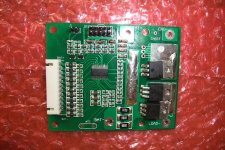
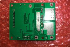
10 cell BMS help.. based on bq77910A T.I. chipset
- Thread starter Ypedal
- Start date
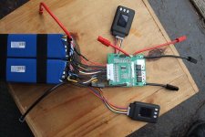
2x 5S zippy 8ah packs, i removed the ridiculous 8awg wire, and installed 12awg, then bridged the packs to make them 10S
They did not include the 11 pin balance lead connectors, so i made my own with RC plugs, and bridged in the 10 cells from + to - to 11 pins.
I also pigtailed 2 sets of wires for monitoring cell voltages, cutoff etc for testing..
Tech specs for the TI chip
http://www.ti.com/lit/ds/symlink/bq77910a.pdf
Also no instructions from the vendor, i emailed and asked but i expect it will be a few days before the sales rep gets back to me from their " engineer " so figured i'd try here in the mean time...
I started by connecting the balance leads, then the Batt - , all was good up to this point,.. then hooked up Batt + and got smoke....
anyone spot the not ?
Now with Batt + not connected, the resistors keep roasting away uncontrolled.... had to pull the plug on everything.
I got 4 more units, so if anyone has any educated guesses on how i might get this right...
I got 4 more units, so if anyone has any educated guesses on how i might get this right...
agniusm
1 MW
My foundingpower bms had rosting issues. I was advised to connect B- first, then sense plug, last charger and controller. Different stuff but might be applicable.
ok, good enough for me, Batt + and - first, then balance wires are next..
crosses fingers. ( no reply from vendor yet )
crosses fingers. ( no reply from vendor yet )
ok.. so BMS no.2 did not smoke... but she's hot.
I hooked up Batt + and Batt -, so far so good, then hooked up balance wires, it started balancing but at least controlled..
the Load - and Batt + show 41v , but as soon as i put a load on, it goes into protection mode... removed load and tried a bunch of times with a tiny 6fet controller and no joy..
Not sure if this is a program issue, i could try to hook it up and flash it with known settings but the vendor did not provide any instructions, there is a two pin J1 and a ten pin J2 pc style jumper pins, the TI spec sheet says it's a serial programming but i got no clue how to go about this.
circuit said:By the way, where did you purchase it? I would be interested in obtaining one sample, especially for larger cell count (two cascaded chips).
Send me an email, i'll fill you in if you really want to pursue it.
....
I have not given up yet.. i just purchased a USB-TO-GPIO unit from texas instruments, 50$ .. And i got a simple diagram outline of how to program it... :lol:
says to provide 14v to J1, easy enough
but only use 1 pin on J2, from the usb programmer, that part seems weird to me, but , will tackle that when i get the unit lol.. if anyone can provide insight i'd greatly appreciate it.
Ok, so Texas Instruments is fast on it's feet when it comes to shipping, 2 days after ordering and it was at my door via FedEx.. well done TI !
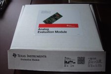
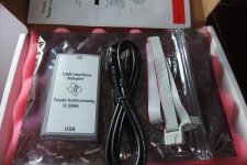
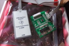
the 10 pin IO cable matches up with the board no problem... the only part i'm not confident about is the 14v DC to J1 .....
anyone have a clue or advice to share before i just plug it in and try it ?


the 10 pin IO cable matches up with the board no problem... the only part i'm not confident about is the 14v DC to J1 .....
anyone have a clue or advice to share before i just plug it in and try it ?
argh.. plugged the USB side to my pc, i get a firmware update error
Detected v 1.16.1
Required v 2.0.19
http://www.ti.com/tool/usb-to-gpio
Searching now for firmware update options
Detected v 1.16.1
Required v 2.0.19
http://www.ti.com/tool/usb-to-gpio
Searching now for firmware update options
http://e2e.ti.com/support/power_management/battery_management/f/179/p/161288/590518.aspx#590518
ref link so i don't loose it.. talking about gui and firmware verison..
ref link so i don't loose it.. talking about gui and firmware verison..
ok, i managed to get the gpio firmware updated to v2, but the evaluation software does not recognize the chip " Target Not Found "
I put 13.3v DC ( 4x lifepo4 cells ) to J1 as shown in the image above.. the 10 pin connector at the programmer and the board are hooked up ..
stuck.
I put 13.3v DC ( 4x lifepo4 cells ) to J1 as shown in the image above.. the 10 pin connector at the programmer and the board are hooked up ..
stuck.
ok, just got this email :
So .. hook up the 36v pack, and then apply 14v to J1 ,...... seems sketchy.. i hope no smoke comes out of this experiment..... :lol:
Please make sure your battery-pack's all terminals were connected with
the BMS
(positive, negative, 11pins of all 10 cells balance pins) correctly
and the apply the 14V DC to J1.
If you still can not start communication between BMS and your PC,
please take a video or
some photos and send to our engineer to see what's the matter.
So .. hook up the 36v pack, and then apply 14v to J1 ,...... seems sketchy.. i hope no smoke comes out of this experiment..... :lol:
How did you update this thing? I can't find any software that is capable of such thing...Ypedal said:ok, i managed to get the gpio firmware updated to v2, but the evaluation software does not recognize the chip " Target Not Found "
I put 13.3v DC ( 4x lifepo4 cells ) to J1 as shown in the image above.. the 10 pin connector at the programmer and the board are hooked up ..
stuck.
i had to dig thru pages of the discussion forum postings on the ti.com site, send me an email and i can send you the required files. ypedal at ypedal dot com.
magudaman
10 kW
So is this BMS worth messing around with. I see the sample kits run about $100 and looks interesting. Any data output to computer through the link.
the TI chip has potential, but the BMS shown here are crap imo... never could get the chip to talk to the GPIO programmer, shipped it to someone else who tried and has same problem.....
Similar threads
- Replies
- 2
- Views
- 426
- Replies
- 5
- Views
- 406
- Replies
- 5
- Views
- 756
- Replies
- 19
- Views
- 982


