BMS wired for charging only

pguk

100 W
Joined
Mar 16, 2012
Messages
111
Location
North England, birthplace of the Industrial Revolu
Hello folks

I'm getting together all the kit for my 1st 18650 pack build. 13s5p. Samsung 35E cells from tumich on here, 20A BMS from cellman. Nickel strips on the boat. Spot welder built and coded by myself.

Now, the reason for this pack build is to replace one I built for my brother 2 years ago, which has been killed by the cheap BMS I used (blown fet shorted pack). He has been gracious enough to commission me to build him another pack - so I want to do I right this time! Hence the cellman BMS. I was reading a comment on ebikeschool.com which suggests it is possible to run the controller directly and not through the BMS, using BMS for charging only. This way I am even less likely to have the same thing happen again. Does anyone have any experience with this setup??
 
Great, thanks for that. I'll give it a go then. I'm ok with electronics so a schematic of the BMS would be good to have?

I've never trusted a BMS for my own builds - I run a hyperion balance charger. But my bro has zero interest in the technical side of things - he just wants a plug and play solution. Like you say, we never heard of a cellman BMS killing a battery :)

Thoughts so far:
1. We can use the smallest BMS to take care of any size battery. Because current is not discharged thro BMS, there is no current limit.
2. Afaik, the reason for running controller thro BMS is to provide for low voltage cut off. This is taken care of by programming in the controller so no problem there.
3. Balancing of cells happens only when charging.
 
this morning I received a reply from Paul at em3ev:

"If you don’t want to use the BMS for discharge, connect the negative directly to the pack negative, therefore bypassing the BMS. I don’t see the point in doing this, if the BMS is capable of delivering the max current that your controller requires."

so that's a very helpful comment from a great vendor. Suggests the idea is a reasonable one, easy to do and I don't have to start with open heart surgery on the BMS!
 
Instead of connecting the bms negative discharge port to the controller, you simply connect the battery negative to the controller, thus bypassing the bms for discharging. The advantage is the bms will never cut power from the battery, The disadvantage is you lose cell level protection during discharge so you must rely on other means as to not over discharge the battery pack. That's usually a function of a properly configured controller lvc, but you can also do it manually with a voltmeter.
 
Can you trust you brother not to discharge beyond say, .....39v under load? (3v x 13 cells) How will he keep track of that?..... Is he interested in keeping track of where his cell voltages are?

:D
 
This is not a new idea - although it's showing up more often these days in smart BMSes or integrated controller devices.

The idea works like this: The conventional BMS is designed to cut the power to whatever is connected when LVC is reached. This is accomplished with a bunch of FETs between the B- (battery[-]) and P- (protected[-]) connections on the BMS. This means the FETs need to be scaled to the load current and must dump a bit of heat due to FET 'on' resistance.

So - to avoid the load current restrictions and eliminate the heat, you can hook the load directly to the B- connection instead of P- and the LVC controlled FETs are bypassed. With this scheme you only need to scale the BMS according to charging current so it has sufficient FET current capacity on the HVC-switched side of things.

However, it's not really necessary to give up the LVC protection on something like an ebike where a controller or CA already plays a critical role in supplying load power. Many common controllers have a power or 'ignition' wire that must be brought to Vbatt(+) and controllers and CAs have throttles that control power application. Either of these can be exploited to allow use of a low current BMS that switches off power not by internal FETs but by a low power signal to the controller/CA.

Using a transistor or FET to invert the normal P- output from (-)=run to (+)=run allows the controller ignition wire to be controlled by the BMS. On LVC the BMS disables the controller logic by switching only 100ma instead of the massive controller current. An alternative is to use a transistor, FET, or opto-isolator to drag the throttle input line to ground on LVC in the same manner as a CA limits controller LVC/current/etc.

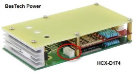
Although this idea can be wrangled with almost any BMS and a few extra parts, BesTech Power sells an HCX-D174 BMS that already has the hookup on board for the controller ignition wire strategy. Just plug the ignition wire into the provided connector and away you go. This particular unit has 15A charge/discharge capacity so some other accessories (DC converter, lights, etc) can be run directly off the P- BMS output. This model is available for LiFe and LiPo/Li-ion chemistries in different 's' configurations.

These schemes do not completely cut off all power dissipation since some bits of external electronics are still operational. This makes them a poor choice for long term storage protection, but they are completely effective for LVC in normal usage to prevent over-discharge under active riding conditions.

Anyhow - this kind of a hookup makes a lot of sense to allow high current bikes to enjoy the benefits of a BMS without the cost/heat penalty of high current BMS FET switches.

HCX-D174.jpg
 
e-beach said:
Can you trust you brother not to discharge beyond say, .....39v under load? (3v x 13 cells) How will he keep track of that?..... Is he interested in keeping track of where his cell voltages are?
:D
Negative. He glazes over when I start to talk about things like amps and ohms! He just wants something that works nice n simple.

wesnewell said:
The disadvantage is you lose cell level protection during discharge

ah! This may be a show stopper for me, thinking about it. A couple of years from now when cells are beginning to be tired, how will we know if one 5p block is going bad? With the BMS wired in as normal, power will be shut down when it detects that a dying cell block has reached the cell level LVC point before the others. Then he'll call me and I investigate before anything too bad happens. Which means trusting the BMS. I popped the top off it the other day and it looks to have genuine ST FETs in there. There are 4 in a row - P75NF75 - 75 volt, RDSon = 11mohm. It is only a 20 A BMS, but he has no desire to be going anywhere fast (we're in the uk = 15.5mph :( ) so it will be sufficient to run the MAC motor.

teklektik said:
An alternative is to use a transistor, FET, or opto-isolator to drag the throttle input line to ground on LVC in the same manner as a CA limits controller LVC/current/etc.

Isn't this how the Fechter/Goodrum BMS works? So you don't lose cell level protection on discharge, and you can still do away with power FETs with associated losses (due to RDS On) /risk of their failing short circuit?
 
It does look like a safer bet to just run the bms as normal if hes not into this stuff like you are. I leave the cellman bms connected for a year in storage and the 16 cells stayed at 3.60v dead.

My ping signal lab drops 4 out of 8 cells to 3.33v (from 3.60v) overnight lol. This started my obsession with riding bareback but regret it now Iv experienced a good bms.

I never got around to it but I was planning to run an led off the bms in place of the old controller wire connection. When the led goes out I know it just tripped lvc but wont cut out on me instantly. Or run a solenoid thats off when powered and on when cut off making a buzzer sound.
 
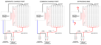
I still don't understand this completely. I've blown 2 BMSs and collateral destroyed a brand new 13s6p battery because of BMS bleeding. So I would like to give this a try. bms-variants.svg.png
 
MotionBlur said:
I still don't understand this completely. I've blown 2 BMSs and collateral destroyed a brand new 13s6p battery because of BMS bleeding. ......

So how long was the battery sitting unused so the bms had enough time to run it down to ruinious?
 
About the time it took:
  • After receiving the cells, Voltage was very constant over all cells, value somewhere around 3.8 V.
  • 5 months later, I assembled them in a pack, same Voltage per cell and charged to 54.6 V
  • 2 month after that, I noticed a drop to 48 V with main switch turned off
  • 2 month after that, total voltage was 2.3 V, where 10 rows in the middle were 0 V and V b-b2 was 1.5 V, V b12-b13 was 0.8 V. Wiring and welding spots were checked very carefully.
 
In the meantime, the supplier confirmed that this, no connections over B- and P-, is the way to go.

I have written it down on http://www.vanderworp.org/Battery_Management_System_BMS.

It raises a question. I've been understanding that balancing is only done during charging. But if charging is separated from balancing as in variant 3, it means that balancing might be active in the range above the control point - being 3.9V for this BMS and becomes inactive at lower Voltages. Is that the way it works?
 
Balancing starts when the bms hits a preset voltage. Balancing stops when the voltage reaches the "bms balance voltage" or lower.

However, the bms will also drain the whole battery at a very slow rate. If a battery is left uncharged with the bms hooked up for a matter of months, the bms can drain the battery to the point of ruining the cells.

It is recommended that any battery pack with a bms attached should not be left unattended for months. If the battery is not going to be used for a long period of time, then the pack should be charged so each cell is aprox. 3.65v and then the bms should be disconnected so it does not slowly bleed the battery down to 2v or less per cell which will kill the individual cells, there-by killing the battery pack.

:D
 
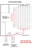
Here's how I interpret the wiring. Please correct if wrong. In my opinion, this is unsafe if your BMS doesn't balance during charge or if you don't give it time to balance. You won't know if a parallel group has gotten unbalanced and it can go below LVC in the worst case when using only the controller's LVC..

bypass_2.jpg
 
docw009 said:
Here's how I interpret the wiring. Please correct if wrong. In my opinion, this is unsafe if your BMS doesn't balance during charge or if you don't give it time to balance. You won't know if a parallel group has gotten unbalanced and it can go below LVC in the worst case when using only the controller's LVC..

yes, If you do not let the battery balance then a group of paralleled cells can be different enough in voltage from the other paralleled groups that they cause a problem. Sometimes it trips the lvc. Sometimes the pack is ruined. If everything is working then simply leave the battery on the charger long enough to balance all the cells. If the battery is not going to be used for a while, charge it to about 3.6v per cell, disconnect it from everything, including the bms and store the battery.

:D
 
MotionBlur said:
In the meantime, the supplier confirmed that this, no connections over B- and P-, is the way to go.

You really connected it that way? Some BMS designs probably need the B- connection to set up the voltage references. Maybe all the balance circuits got turned on and flatlined your battery.
 
docw009 said:
MotionBlur said:
In the meantime, the supplier confirmed that this, no connections over B- and P-, is the way to go.

You really connected it that way? Some BMS designs probably need the B- connection to set up the voltage references. Maybe all the balance circuits got turned on and flatlined your battery.

I haven't connected anything yet. I'll ask the supplier if he's sure. Flat lining happened with a separated charge wire BMS (the first picture). Considering it totally drained the batteries, from 48 V to 2.3 V, in only two months, I think the BMS was faulty. I'll open it up one day.

Apart from double safety, I can't see a reason not to trust the controller for low Voltage protection. However I am glad you stressed the importance of the balance function. In fact, I tend to consider buying 14 V and 13 A meters, just to get a better understanding during charging and balancing.

As @e-beach suggested for storing, it is also tempting to let balance wires run over a GX-20 14 pin connector to make this easier. All in all, I am not sure where I'll end...
 
MotionBlur said:
..... Considering it totally drained the batteries, from 48 V to 2.3 V, in only two months, .....

If your BMS was connected to your battery and the battery was stored and not used or charged for two months, then the bms slowly bleeds the battery to nothing. Probably nothing was wrong with the BMS, it was one of the type that would do that. Most BMS's will probably do that.

Rewiring a BMS in some "Odd" way is not the answer. The answer for storing a lithium battery with a BMS for an extended time, is to disconnect the BMS. The other option is to keep it plugged in to an applicable charger that is plugged into a outlet so it can maintain the charge, and just leave it like that.
 
e-beach said:
If your BMS was connected to your battery and the battery was stored and not used or charged for two months, then the bms slowly bleeds the battery to nothing. Probably nothing was wrong with the BMS, it was one of the type that would do that. Most BMS's will probably do that.
I made two packs at the same time, with same components. Only one was completely drained after 2 months, so my conclusion - after checking everything else - is that the BMS was faulty.

e-beach said:
Rewiring a BMS in some "Odd" way is not the answer. The answer for storing a lithium battery with a BMS for an extended time, is to disconnect the BMS. The other option is to keep it plugged in to an applicable charger that is plugged into a outlet so it can maintain the charge, and just leave it like that.
I understand why you think it is "Odd", let me explain. I don't like chargers, just like TV's, turned on in an unattended way. Remains unplugging the BMS. JST 14 pin connectors are not made for frequent connect and disconnect cycles, they are to fragile. So I don't think it is that "Odd" to seek a better fitting solution by choosing a rigid GX-20 aviation plug.

It will take some time to build it all again, surely I'll share my findings and thanks for the help so far.
 
I'm thinking on the same, I don't want to purchase a 100A BMS, so bypassing the 60A BMS and setting the controller's low voltage limit is the way to go. Plus I'll add fuses and a circuit breaker. A good pack shouldn't have imbalanced cell pairs, SLA battery packs doesn't have a BMS either, but I'm using mine for 3 years and it's still in a good condition, which is rare. For li ion, take your time and test all the cells, before assembly (that's what I'm doing now, testing 280 cells) and then take an average, for example if you have 4 cells with capacities like 1Ah, 1Ah, 2Ah, 2Ah, the average is 1.5Ah multiply it by the number of your parallel connection (let's say we want 2 so the average parallel connection capacity is 3Ah. Connect the 1Ah and 2Ah in parallel and there you go). That way you can assemble a pack with the least differences, it's important, because the BMS only balances with a little current, like 30mA, so if the difference between the cells connected in series is over 30mAh (which doesn't sound too much but it is) it will take over 1 hour to be balanced. Also if you assemble your pack with different cell voltages, the BMS will never balance the cells together. I learned that the hard way, half of my cells arrived at 3.77 V the other half at 3.66 V, I thought it will be fine, but the final charged voltage was around 57,2V instead of 58.8V. The pack was completely ruined after a year (15ah instead of 33Ah). Now I disassembled my pack and testing the cells.
 
john61ct said:
You've resurrected a zombie thread over three years old. NG
LOL! Yet, times change. A BMS for the sole purpose of upper and lower Voltage... Currently I balance during charging with those "flying capacitor" boards and working Voltage is monitored by the motor management during riding. Bye BMS board is tempting ;)
 
Back
Top