kWeld - "Next level" DIY battery spot welder

tatus1969

1 kW
Joined
Mar 17, 2017
Messages
396
Location
Germany
Hi guys,

as part of my kicksurfer project (I was tired of my battery pack manufacturer of wanting >700€ each time I am asking him to prepare a few samples of packs from another cell type), I have started desigining a DIY spot welder.

After some googling, I realized that even when building it myself it would be quite costly, as the required power source needs to have very high specs. A suitable capacitor bank for example would be 100€+.

As I am using cheap race Lipos with 200A current rating for my RC car, I thought that they might be capable for welding as well. A first measurement then showed 1kA into a short!

I am still at the beginning, but I want to share my experience, and at the end make this open hardware that others can copy or build on.

The design thread is here, I hope it is not forbidden to link to a different forum but it is quite time consuming to keep multiple threads with the same subject.

http://www.eevblog.com/forum/projects/guesses-on-what-i-am-attempting-here/

Please let me know what you think, and I would be happy to hear if anyone would want to build one (after it is finished and stable).

xxxxxxxxxxxxxxxxxxxxx

Batteries that have been successfully used with kWeld

ODYSSEY Extreme PC925 12V Auto Battery, 28 lbs
https://endless-sphere.com/forums/viewtopic.php?f=14&t=89039&start=1125#p1556817
 
Thanks for the link, that has saved me an experiment. I will directly continue with board layout, the FETs will certainly do the job.
 
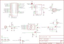
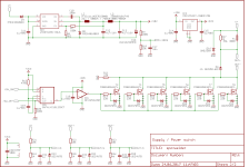
Updated schematics (rev.1).

spotwelder-sch1.png
spotwelder-sch2.png

I plan to implement an energy based pulse control instead of a simple timer. i will try to see how that works with one single pulse, maybe that eliminates the need of a cleaning pulse. Constant energy delivered to the weld spot should result in more consistent welds. The circuit should also be able to detect a failed weld, in this case the requested energy cannot be delivered in a reasonable time.

What do you think about this approach?
 
That looks very nice. It's always a good thing to see several development projects evolving for the same purpose, we never know which one will have which strengths...
 
Good to see another design, i have two, both came out of here. Both are better than the sunkko fron China. Watching to see how you roll.
 
I hope that it will also perform nice, it should be good for up to 4kA / 10ms and up to 36V. I estimate 80€ for an assembled and tested / programmed board. That's not too low cost, but I hope the new features justify that. The probes, wiring, brass parts, bolts and nuts should be <10€, I am not sure if it would be better to provide them as well or not. If yes, there would be some machining involved for the brass parts, maybe 30 minutes per kit. Plus the cable confection. The power source itself, in my case a 5Ah/3S Lipo, will not be part of the kit.

As I wait for board and parts, I have started coding. Stay tuned 8)
 
Most software parts are prepared, the weld control loop already works with 10us cycle time and ADC conversions running with DMA. Really nice microcontroller architecture, you set up everything, and then it will continuously update an array in memory with conversion results.

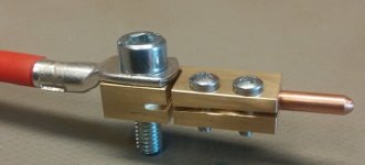
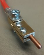
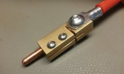
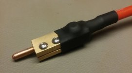
While waiting for the boards to arrive next week I have machined electrode holders from 6x12x35mm brass. What do you think about it (these are not the final screws yet)?

IMG_20170702_123949.jpg
IMG_20170702_124000.jpg
 
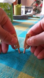
It's hard to tell without some sense of scale. They look rather large?
 
this should give a better impression. I was looking for a solution that allows easy electrode replacement. These are made from a 4mm dia copper rod.

IMG-20170703-WA0003.jpg
 
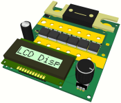
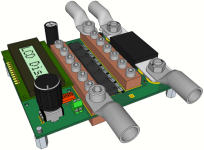
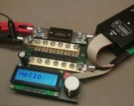
The boards have arrived earlier than expected. That allowed me to use the evening to solder and assemble one. So far everything seems to work! High current tests to follow.

View attachment 1
IMG_20170704_234859.jpg
 
Looks fantastic work to me, I'd definitely be up for having a go at building one.

I'm in the middle of replacing a Triac on my sunko + I've just ordered some 3mm copper rod, would much rather be playing with this than the sunko. Nice work!..
 
mxer said:
Looks fantastic work to me, I'd definitely be up for having a go at building one.
Thanks :D If my design proves to work reliably, then I will definitely run a batch at Elecrow. I hope to get to that point during this weekend.

mxer said:
I'm in the middle of replacing a Triac on my sunko
I hope the price of that part did not exceed the cost of my entire device :wink:

Yesterday I learned three things:
1) a multichanel ADC has a source for offset errors that I didn't realize before. When you look into my circuit diagram, you'll see that the MOSFET voltage measurement (OUT-) has a 10k filter resistance. According to the STM32's datasheet, that would be enough to settle to <1LSB at full speed. But I measured ~50mV at the ADC input, even with the MOSFETs shorted. Where did that come from? The ADC appnotes from ST didn't give a hint either. It took me half of the evening to figure out that this is charge injection from the previous conversion. The ADC configuration is to continuously convert all five available channels one after another. Therefore it has a MUX that connects one of the inputs to the ADC input. That input has a capacitance. If, as in my case, the channel that precedes my problematic one has a siginifcantly higher voltage level, then the ADC input capacitor is charged to that level when switching to that channel. This dumps the stored from energy that capacitor into the ADC input network. As this is done repeatedly, this causes a constant current flow. The ADC input capacitance is 8pF, and the conversion rate is approx 100kHz. Assuming the adjacent channel sees 3.3V, and my problematic one has 0V, the current calculates to 100k * 0.5 * 3.3^2 * 8p = 4.3uA. The voltage drop on the 10k resistor then calculates to 43mV. Gotcha!

2) a buck converter with bootstrapped power switch driver can never live with an output capacitor (in my case 2200uF) that 'survives' zero input power longer than the bootstrap capacitor. When the input voltage comes back, then there is nothing that can charge the bootstrap capacitor (as the output almost equals the input). This situation is only resolved when the output voltage has dropped far enough for a restart, unluckily leaving the supplied circuit dead during that time... Solution: move the freewheeling diode from the input to the output of the regulator. Luckily I can do that because I do not need a precise voltage.

3) the ADC inputs of the STM32 are not 5V tolerant. If I would have noticed that earlier, then I would not have to replace a dead microcontroller now. As I need a low leakage input protection, and a zener diode just doesn't deliver on that, I ordered some TL431. They will protect the OUT- input from high voltages.

Luckily the microcontroller did not die before allowing me to make this measurement. (Yellow: voltage across ~700uOhm of AWG8 wire, blue: voltage across MOSFETs) I don't believe the readings yet (why does blue approach zero??), but it suggests that the pulse current (here, into a 100% short circuit) is in the order of 1.5kA. Scary.
 
tatus1969 said:
this should give a better impression. I was looking for a solution that allows easy electrode replacement. These are made from a 4mm dia copper rod.


Thank you! Nice size, IMO. I have to say, the other resently posted design with a single handed two electrode design is more attractive.
 
Really nice looking board. About the only thing I would worry about is the board foil carrying all the current the short distance from the FETs to the bus bars. Some Riba welders managed to blow the foil off. If the copper is heavy enough, no problem. Alternative is to add copper where needed.
 
tomjasz said:
Thank you! Nice size, IMO. I have to say, the other resently posted design with a single handed two electrode design is more attractive.
I delibarately opted against that. I am afraid that it can be difficulty to distribute the required mechanical force evenly. I think that the solution should be spring loaded then. But even more important for my design, I want to implement an automatic mode that does not require a foot switch. The controller detects that you connect the electrodes, waits for a certain time, and then fires automatically.
 
fechter said:
Really nice looking board. About the only thing I would worry about is the board foil carrying all the current the short distance from the FETs to the bus bars. Some Riba welders managed to blow the foil off. If the copper is heavy enough, no problem. Alternative is to add copper where needed.
Thanks :D I am also afraid of that. But the board is double sided, and if it is not strong enough, then I can double the copper thickness. The cross section is approx 2.3 mm^2 for the top layer, and the length is 0.5mm. This makes a resistance of 3.7 micro ohms, and at 3kA the power dissipation would be 33W. That should hopefully work out even without bottom layer. And I have deliberately made the bus bars thick for good heat transfer, otherwise they are overdone even for these currents.
 
Interesting side note:

I have just finished completing the firmware code but cannot test it, because UPS didn't deliver the missing parts today as scheduled. This is the information that UPS gave me this morning:

Unbenannt.png

Something is wrong with this information - who can tell me first?

Hints:
a) it has been sunny and calm for a few days now
b) I live near Hamburg, Germany
 
Yes! 8)

This is 0.1mm Hilumin.

A video showing the welder in action is in preparation!

IMG_20170709_000425.jpg
 
Back
Top