Looking for advice on my 18650 build so far

sailah

1 W
Joined
Aug 13, 2010
Messages
52
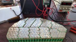
Building a 20S12P pack for my Qulbix Q76R. Followed Quokka build pretty closely.

(240) Samsung 25R cells
0.2mm pure nickel sheet
Supower 100A BMS

8kw controller from PowerVelocity
QS205 motor

I've almost done all the spot welding just the +/- connections and BMS.

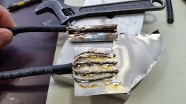
I'm having second thoughts if I should add some copper to go along with my nickel.

The other thing I'm struggling with is how to attach the leads. My plan was to solder the B- and Pos to a nickel sheet and then spot weld that to final connections. I have a Hakko soldering station but 8g seems to tax it and ends up getting everything hot. Thinking I need a soldering gun in the 150W range?

Waiting for lots of connectors to come in from HobbyKing so would like to have a game plan when they come in. Read lots of threads but haven't seen a great solution that stands out to me.

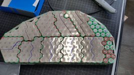
Here's where I am and some tests I did. Tried "wrapping" the nickel around the wire but that didn't work well. Separating wire to 4 strands was too much for my Hakko. The other side of the pack has #1 & #20 for +/- and those have not been spot welded yet.
 

Attachments

  • 20180218_151918.jpg
    20180218_151918.jpg
    238.4 KB · Views: 1,584
  • 20180324_180536[1].jpg
    20180324_180536[1].jpg
    291.2 KB · Views: 1,584
  • 20180325_095352.jpg
    20180325_095352.jpg
    181 KB · Views: 1,584
Here's pack awaiting final connections
 

Attachments

  • 20180325_124024.jpg
    20180325_124024.jpg
    249.3 KB · Views: 1,582
What's your controller'peak amp draw. I'm thinking you're going to be tripping that bms with even moderate use. And it'll die pretty soon potentially taking your battery with it. Had a supower bms do that recently.
 
Says battery current to 70A, phase to 200A

http://powervelocity.com/index.php?id_product=48&controller=product

Honestly everything wiring wise looks wimpy. The controller wires are a magnitude thinner than the phase wires from the motor. And the BMS wires are also thin although there are 2 wires for each connection.

I don't want to do the battery over again which is why I'm going heavy 8g wire for that. I bought the biggest BMS I could find for 20S at the time. If there is a bigger BMS I'm all ears, I also think I should have gone bigger on the controller but was talked out of it by the guy from PowerVelocity.

This is my first ebike but I've built quite a few custom adventure motorcycles. I'm solid on the machining and fabrication but the electric stuff is all new to me.

Thx
 
Oh my gawd!! That battery! :shock:

That bike is gonna scream once you have it going. That's gonna need one heck of a charger too.
 
Philaphlous said:
Oh my gawd!! That battery! :shock:

That bike is gonna scream once you have it going. That's gonna need one heck of a charger too.

Thx, I hope so I just don't want to regret going small on components with how much time I have invested so far. I bought (2) Meanwell HLG-240-42 power supplies and tied them in series. Should be 5.7A @ 84V. They are CC/CV. I adjusted voltage down to 83.8, so 4.19V per cell.

I also have a 50V 20A Cisco server power supply en route from ebay I bought for $12 shipped :shock: . Would pair well with my 40V 20A Sorensen linear power supply for some real watts. Have to figure out how to get the Cisco to turn on, originally I bought a bunch of those HP server supplies, 700W each but I couldn't run on 120V outlet. I'd rather be safe charging than speed.
 
Why 4.19? 4.2 vs 4.19 isn't going to be much different as far as saving the cells over time. I've read 4 or 4.1v is much better.
 
No reason, was just tuning the charger using pots. Can easily get to 4.1V if needed, thx.

Here's a photo showing various controller, BMS and motor wires for size comparison
 

Attachments

  • Capture.JPG
    Capture.JPG
    251 KB · Views: 1,549
Hmm yeh I see what you mean. If you're not using full power for long periods then you should be ok with BMS- hopefully the 30amp buffer will keep it cool on the blasts!
The one I replaced died and took out P group one with it :x i think that channel died as a result of the closet MOSFET getting super hot shorting and heat damaging the components around it.
But it's looking pretty good for a first build! Just monitor everything for heat before you go to stupid :) . maybe stick a spare jst plug paralleled to the bms one and bring it out of the insulation so it's easy to access. That way you can check cell Vs easy anytime and keep a human eye on your pack. Cause bms's can be the stealth battery assassin's. Quietly but surely destroying your $$$ battery ( and your will to live when you find it!!)
 
Thanks kdog.

The more I think about BMS the more I'm inclined to bypass it. I have a controller with programmable LVC which is readable via bluetooth to my phone. I don't plan on pushing the battery to LVC limits, quite the opposite.

So as I see it, the BMS really is just for balancing in my case since I'll be using alternate methods to check LVC. I guess the danger here is that if 1P gets out of whack I won't know since I'm only looking at aggregate voltage.

What about one of these new blutooth BMS just to monitor parallel groups? Or as you say use an external JST plus and check voltage periodically?

Use a cell meter and switch through the packs while charging?
 
Use a good (dewalt) hot air gun for soldering those leads... Set to 500deg + and you will melt the solder very quickly. Tin the leads first or you will burn the wire.

If no BMS then run balance leads to a plug/s so you can balance with a hobby charger.
 
Thanks for comments sorry was delayed in response.

I decided to run BMS but only for charging. Ran all balance leads, connected B- to pack. Ran charger lead to Pack + and BMS P-. Made up sleeved charger leads with XT60 connectors. Mates with bike Neutronix Speak ON lead I also ran.

Covered pack in 3mm adhesive foam with cutouts for all wires. Foamed bottom of BMS and then hot glued to pack.

20180408_112912.jpg

My shrink wrapping went okay for first time. I cut the wrap too short and it doesn't fully cover the ends. I should have done those first and then did an external wrap. Oh well, it's an easy fix.

20180408_115604.jpg

I'm now asking questions about things like circuit breakers, chafe protection and connectors.

I bought a 100A Midnight Solar DC breaker. Assume I hook that up inline from pack + to Controller +? Thinking I can secure in bike cavity with VHB tape and some type of boot over studs.

I plan to use some lexan angles to act as skids for pack where it would bear against the frame. My pack fits VERY snugly (too snug) in channel created by frame. But in my mind there isn't enough clearance to feel comfortable with that. The lexan angles would help space the pack off the frame and help with chafe. I'll need to redo the Qulbix side panels too.

Also connectors. I'm running 8AWG cables from pack. I bought a ton of connectors from Hobby king. I think I pretty much bought every type they have lol.

I have these really huge 8mm bullets which are too big.

XT150 seems about the right size. I have some XT90S on the way too.

Am I right that the solder cup is tiny? Fill that, tin wire and assemble with solder? The depth of that cup is only 3mm. I don't have a crimper that will fit that although I might. Was also thinking of machining up some new pieces out of brass with deeper cups but I'm probably overthinking it.
 
Back
Top