iCharger 4010 Duo review

ElectricGod

10 MW
Joined
Nov 1, 2015
Messages
3,404
Location
3 OH 3
A couple of months ago I did a review of the Chargery C1042B. I was pretty scathing since those chargers are giant piles of garbage. I still wanted a high wattage, many cell charger so I bought this iCharger 4010. I paid $300 for it...so not exactly inexpensive. One of the things I was curious about is if it had any of the issues the C1042B has. I can emphatically say that it does NOT have any of them.

iCharger%204010%20duo%20top%20view.jpg


1. The LCD is a lot brighter, clearer and higher resolution. It can be viewed in direct sunlight and while not an IPS LCD, it's a decent TN display that can be read at angles.

iCharger%204010%20duo%20LCD%20screen%201.jpg

iCharger%204010%20duo%20LCD%20screen%203.jpg

iCharger%204010%20duo%20LCD%20close-up.png


2. The charger can be left connected to a battery pack for weeks at a time and NOT run down the cells. It balances well and there is no hint of over charging one cell over another.

3. The charger is a good bit smaller than the C1042B, but then it has no internal power supply.

4. The design of the charger is neat and clean with no extraneous inter connections. It's far better designed than the C4012B...which is just garbage. If there is one thing I like more about the Chargery C4012B it's the aluminum shell.

It comes with these cables and balance boards.

iCharger%204010%20duo%20cables.jpg


I do have a few minor complaints. Otherwise...this is a brilliant charger.

1. You need your own PSU. I already had one so that was not a big concern to me. However for a lot of folks dropping $300+ for the charger and then buying a $75 PSU makes this a fairly expensive purchase.
2. The large capacitors on the board are not secured except by their legs.
3. The ribbon cable from the main board to the top cover board is too short and has fairly fragile connectors.
4. For a charger this expensive it ought to have BT, android/IOS app and a PC app. It has none.
5. THe power input isn't an XT90...which are cheap and super common.
6. The 2 power output cables had bare ends. I had to add my own XT90's.

So then...onto some exterior pictures...

iCharger%204010%20duo%20front%20ports.jpg

iCharger%204010%20duo%20fans%20and%20rear%20connections.jpg

iCharger%204010%20duo%20underside%201.jpg

iCharger%204010%20duo%20underside%202.jpg


The bottom comes off with 5 screws and then slides off easily to reveal this monster heat sink.

iCharger%204010%20duo%20heat%20sink.jpg


The top is held to the board via 2 screws. Once they are removed there's this short ribbon cable to disconnect. It's connectors are quite tiny and fragile so it's good to NOT pull on it in any way. The ribbon cable is about 2" long. It would be a bit easier to unplug if this cable was another inch longer.

iCharger%204010%20duo%20ribbon%20cable%202.jpg


Once the top is pulled off there is a small board that has the switches on it and a smaller ribbon that goes to the LCD.

iCharger%204010%20duo%20top%20underside.jpg


The CPU says "ARM" on it...so I can make a fairly good guess what this CPU is based on it's pinout and and shape. Otherwise...they have etched off the top of the CPU. Notice that tiny connector. This is where the ribbon cable to the top cover connects. It's all of 1/2" long and that black plastic part is super fragile.

iCharger%204010%20duo%20CPU%20and%20ribbon%20connector.png


A few pics of the top side of the charger main board...

iCharger%204010%20duo%20main%20board%20top.jpg

iCharger%204010%20duo%20capacitor%20close-up.jpg

iCharger%204010%20duo%20power%20connectors.jpg

iCharger%204010%20duo%20shunt.jpg

iCharger%204010%20duo%20%20balance%20components%201.jpg

iCharger%204010%20duo%20input%20power%20and%20fuses.jpg

iCharger%204010%20duo%20%20hillrc.com.jpg


The underside of the main board...

iCharger%204010%20duo%20%20balance%20components%202.jpg

iCharger%204010%20duo%20%20balance%20components%203.jpg


The board is held down to the heat sink by 8 screws. All the screws are strategically placed at mosfets or where they provide the best support and clamping pressure to the mosfets and heat sink.

iCharger%204010%20duo%20hold%20down%20screws.jpg

iCharger%204010%20duo%20hold%20down%20screws%202.jpg


The bottom of the board.

iCharger%204010%20duo%20main%20board%20bottom.jpg


The heat sink has 2 pads of thermal gap filler that sink heat away from the 20 balancing transistors. The 11 places for the mosfets have glass insulators with heat grease on them.

iCharger%204010%20duo%20heat%20sink%20bottom%201.jpg


This is the balancing transistors. They have fairly large resistors underneath them. I expect 2A balance current is quite possible.

iCharger%204010%20duo%20balancing%20transistors.jpg

iCharger%204010%20duo%20%20balance%20components%206.jpg


The charging logic.

iCharger%204010%20duo%20balancing%20logic%201.jpg


All the mosfets have very short legs and they are reinforced with solder. This ought to make them handle the maximum current possible with the best heat transfer.

iCharger%204010%20duo%20mosfet%20leg%20close-up.jpg


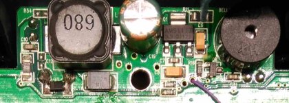
A small DC-DC converter for powering the logic.

iCharger%204010%20duo%20dc-dc%20converter.jpg
 
I made a bunch of videos of the charger. I started with it all disassembled and went backwards to assembled and charging.

1. https://youtu.be/bbq_uVOTZLc
2. https://youtu.be/eoq_r3QB6Ag
3. https://youtu.be/d3JWzkipkYY
4. https://youtu.be/aWJND83xOKk
5. https://youtu.be/aXQvJRMORGw
6. https://youtu.be/zrH6t0uZgXw
7. https://youtu.be/Vi45lFCqNlI
8. https://youtu.be/CRdtZiXjyGs
9. https://youtu.be/zrbYvX9yBsY
10. https://youtu.be/u_yHOfncw5o
11. https://youtu.be/_-eoslT0qqY
12. https://youtu.be/Q-i8F9ExJVw
13. https://youtu.be/OVm2kudAhaU
 
tahitiboob said:
thanks you for the review i have this icharger and i am very satisfaid

For people that want/need a high wattage charger with a high cell count, this is it. I'm pleased with my purchase so far.

It is common that chargers will have a pretty decent charge current, but discharge will be like 200mA. The C4012B chargers could discharge at several amps...which is great for load and capacity testing batteries. I have an ISDT D2, SkyRC D100 and a couple other chargers. All of them while they have settings for far more discharge current pretty much do 200-250mA. The iCharger 4010 has discharged 6S at 5 amps for me. I haven't tried higher current than that yet becasue I've been messing with 18650 cells.
 
I googled for "icharger 4010 duo software" and got to here. You can find the latest firmware upgrader and the logview app. The software at the manufacturers site is older.
https://www.progressiverc.com/duo-updates

A good video on tips and tricks for the 4010 DUO.
https://youtu.be/HRdotaxM3pQ

Go here: http://www.logview.info
And download the logview app. Apparently you can at least see status of what has happened in the charger.

In the manual is this URL. They have everything published so there could be a USB PC app for this charger, but then no actual app.
http://www.jun-si.com/UploadFiles/iCharger_MODBUS_Protocol.pdf

I think this is the actual manufacturer for the charger. The board says hillrc.com on it.
http://www.jun-si.com
or
http://www.hillrc.com

Going here: http://www.hillrc.com/Endownload.asp
I find iCharger_USB_driver, iCharger_Manual, iCharger_upgrader and iCharger_CD-ROM

As it turns out the iCharger_CD-ROM file is old content and contains the USB drivers, upgrader and logview app. You want to get the separate USB drivers and upgrader and then go to the logview web site to get their latest version. Just go to the progressiveRC site instead. That content is newer.
 
From what I understand the 4010 duo is also now Modbus controllable.
So you can pretty much do a whole scenario using a pc on the side to control it with.

I cannot rember if it was in a thread on this forum or if it was on the RC forum.
I'll do a quick search.....

https://www.rcgroups.com/forums/showthread.php?1801512-New-iCharger-4010DUO-308DUO-406DUO-Have-Been-Released%21%21%21

This is the master thread for the units.
Search that and you will find about the modbus capabilities and also some downloads that can be used.....

Best Regards
/Per
 
pm_dawn said:
From what I understand the 4010 duo is also now Modbus controllable.
So you can pretty much do a whole scenario using a pc on the side to control it with.

I cannot rember if it was in a thread on this forum or if it was on the RC forum.
I'll do a quick search.....

https://www.rcgroups.com/forums/showthread.php?1801512-New-iCharger-4010DUO-308DUO-406DUO-Have-Been-Released%21%21%21

This is the master thread for the units.
Search that and you will find about the modbus capabilities and also some downloads that can be used.....

Best Regards
/Per

Thanks for posting this. The USB interface has commands for everything in the charger as far as I can tell. I should be able to set either channel to do anything via the USB interface. There ought to be an app for controlling the charger via a PC. So far I haven't found one.

Something I haven't found yet, but I bet this charger can do it is create a new battery type that it doesn't currently list. I have about 240 LTO cells I'd like to test on it. LTO works at 1.9v to 2.8v so changing the max and min voltages for something else isn't really doable.
 
I can say Ive used every iCharger made and have been a dealer. The Duo line is great. I used them to charge my stable of Multistar batteries. Sometimes both channels are charging 6s and other times I do 4 and 6s. I have used these chargers at 100% of their capacity and they do it without breaking a sweat. Ive charged 6s batteries at 40A on both channels with a 36v 62A PSU and it handled it great. I personally like the 406 Duo. Ive had one for 4 years of faithful service. You made very valid points on some of the internals. Ive used EC5 connectors and never had an issue. I also wanted to do some mods like bring the connectors from the front and solder some 6 inch 8AWG leads terminated to EC5 or XT90 just so you arent so restricted and cluttered up by the front of the charger. I think the input could use some recapping with larger lower ESR caps.. the whole unit I think could be recapped for reliability. I probably would reapply good thermal compound all around. Beef up some of the traces with more solder. It could use more cooling. So maybe a 3d printed stand with like an 80mm fan blowing on the heatsink could be an improvement. The 2A of balancing current per channel is great and even better when the charger is in synchronous mode. Ultra precise balancing and even allowing you to tweak the profiles for a more complete charge on the top end.
 
Is this the newest version 4010?
I see you have smd fuse at pcb, how many amps are they ?

Looking at my smoked 4010, I can't find any smd fuse soldered.... :oops:
 
Never mind I have just a look at my smoked 4010, I have version V14, so a old version.
At least they have fixed the problem for shorting problems.
 
From my experiences I will not buy this expensive charger again.
You will not be able to repair by yourself, everything has been scratched out and customer service will not reply to you questions.

Running time for this charger was only few times in a half year.
 
I alao blowed one channel but repaired it and still working great.
I think i made a thread in this forum also for my problem i guess.
 
BoomerChomsi said:
Just a a fet or more components were blown out?
fuses and one diod :) I was lucky i think considering what I was doing with it :shock:
In that post i have pictures also about blown components.
But this charger has two identical sets, so if you blow one side you can get blown parts numbers from another side.
https://endless-sphere.com/forums/viewtopic.php?f=34&t=68543&start=100#p1369449
 
Thanks! :bigthumb:

I see thy have a new version PCB to protect fets by adding fuses at positive outputs.
Any info about the diode?

When I have time I will try to repair my charger again.
Blown fets, blown diode, also fet driver adrea is also suspicious.....
At last I hope balancing area will still work after repair..... :oops:
 
I measured the diod and installed similar one and it worked. I even installed not SMD diod using wires.

After have fully charged my 7s lipo using 48V power supply I connected 50,7V (4x12V pb in serial) to input and something blow inside. I think I had my lipo also connected to balance port just forgot to remove it. Does anybody know what this ise?
 
BoomerChomsi said:
Forget to asked, partnumber/type of your diode?
You mean the diod I replaced. I can't remember and right now it's behind heatsink I do not need to remove this time.
I desoldered that diod from scrap electronics but it's parameters were similar to the working one, that was intact from my last bang :)

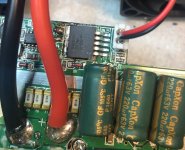
PS! I figured out what this Voltage Regulator is: LM2576HVS and 5V output version because there is 6,3V CAP connected to output and fans are also 5V versions. Ordered myself a new one and it arrives in monday, hoping that replacing that I can bring charger alive 8)
 
Replaced this Voltage regulator and charger started to work with 12V laboratory power supply output.
IMG_4880.jpg
Had to replace that 6,3V CAP also because it was a little puff to the eye. And it was only after I tried with 15V meanwhile.
Then I turned charger off and upped voltage to 35V and when turn on there were smoke.
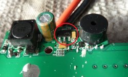
And it seems the chip that is on other side burned 3 small legs and one big leg. Found this picture in this thread that has some visible numbers on that chip (in my chip there is nothing visible anymore)
iCharger 4010 duo dc-dc converter.jpg
 
BoomerChomsi said:
Forget to asked, partnumber/type of your diode?
Was searching the net today and stumbled accross this youtube video comments: https://www.youtube.com/watch?v=YT_eKgLiIgo

"Junsi Electronic Co.,Ltd just got back to me. It is a not a Schottky-Diode (to honor the guy, please spell it right) but a TVS -Diode. Name is "SMBJ43A"."
 
Hi nuxland! Yeah, that was me posting the diode typ. Been watching this thread for a while but on my phone I can not post a reply. At home I always forgot about it.

I looked at my icharger pcb. Thats what I found.

Its an old board design. No fused on the pcb.
 

Attachments

  • IMG_20180624_010820 blowup.jpg
    IMG_20180624_010820 blowup.jpg
    77.6 KB · Views: 4,890
Haha funny for first time I have looked a yoube repair video, also found this video yesterday.
Normally they are not very useful, but this time :bigthumb:

Thanks anyway for sharing :bigthumb:

I am surprised why the dc converter fet smoked out... :oops: :?: :?:
 
Back
Top