Samsung 40T - 35A 21700 Li-ion battery's capacity test

thunderheart

100 W
Joined
Oct 8, 2017
Messages
219
Location
Armenia
Original article: https://www.thunderheartreviews.com/2018/12/samsung-40t-high-drain-21700-li-ion.html

I've tested the Samsung INR21700-40T (35A) at up to 20A discharge (limited by my equipment).
221767_original.jpg


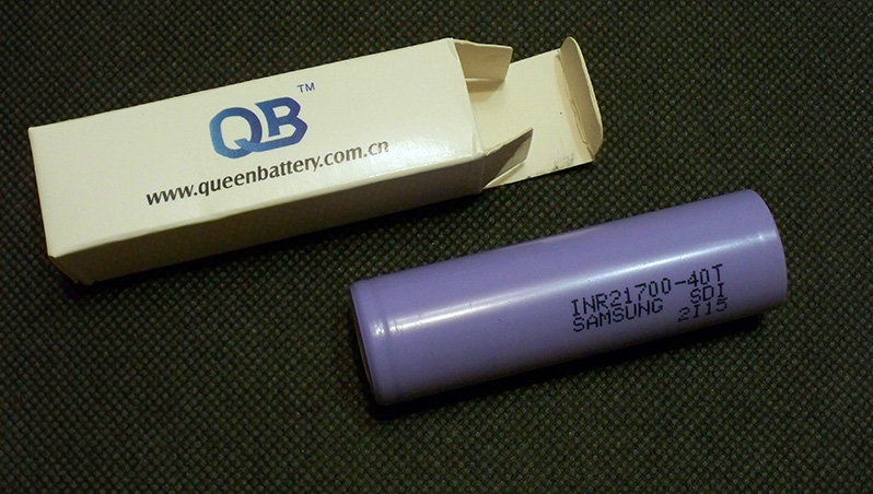
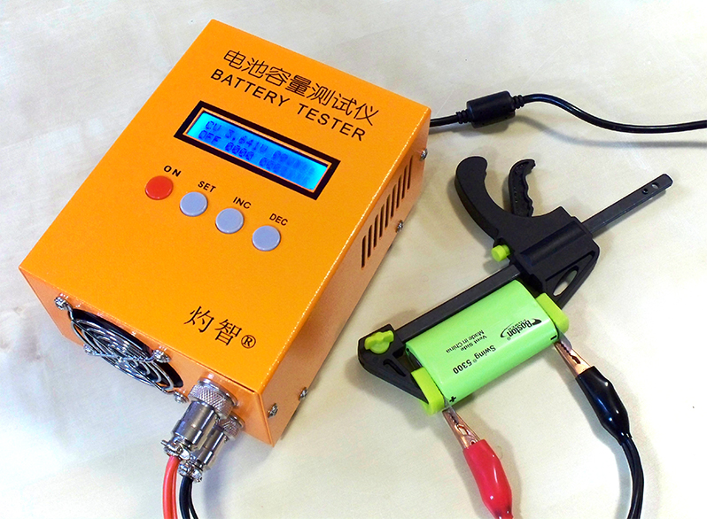
The battery was bought from my reliable supplier (Queen Battery) and tested with ZKETECH EBC-A20 and a self-made battery holder. It's a PC-connected battery tester supporting 4-wire measuring and discharging at up to 20A.
87638_original.jpg


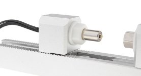
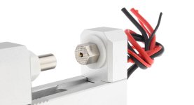
I've used version 3.0 of my battery holder based on 0.5mm thick pure copper terminals
210421_original.jpg

209931_original.jpg


I've followed all the prescriptions of the IEC61960-2003 standard concerning battery's capacity measurement. Before each discharging cycle each battery was charged at standard charge current mentioned in its datasheet to charge end voltage. Before each discharging or charging i've held a 1-1.5hrs pause. The environment temperature was 23.5-24.5°C. To be sure in results i've done each test minimum twice (usually 3-4 times).

Samsung INR21700-40T
The cell is marked as INR21700-40T SAMSUNG SDI 2I15 which means that the production date is 05 Jan 2018.
221029_original.jpg


The main specs from Samsung 40T datasheet:
Capacity: 4000mAh
Nominal voltage: 3.6V
Standard charge current: 2A (200mA cut-off)
Fast charge current: 6A (100mA cut-off)
Charge end voltage: 4.2V
Max. continuous discharge current: 35A or 45A with 80°C temperature cut
Discharge cut-off: 2.5V
AC impedance at 1KHz: 12mΩ
Max weight: 70g

Measured DC IR at 4A in fully charged condition was 12±0.5mΩ

Measured weight of the tested cell was 66.57g
221353_original.jpg


Test results:
220887_original.png

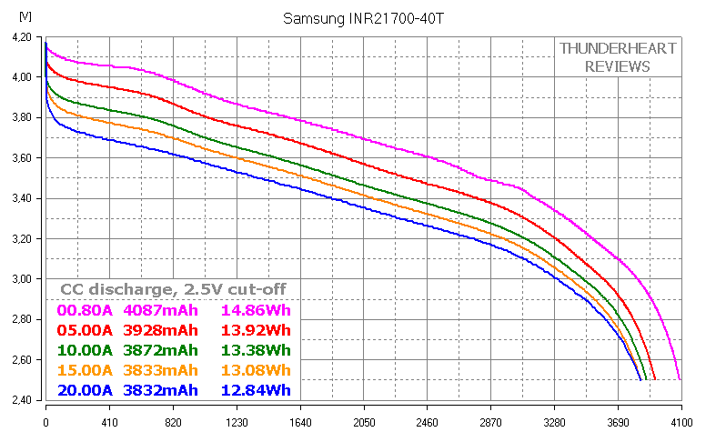
At 0.2C (0.8A) capacity is almost 4100mAh and it doesn't go below 3800mAh even at 20A discharge! Curves look beautiful, without abnormal sags.

This cell is the evolution of 30T which i've tested before and it brings the capacity of high drain 21700 cell to a new level. It also supports 45A discharge but at discharge rates above 35A the temperature must be properly controlled.

Here is the video version of this review


Check out my YouTube channel for batteries, chargers and other stuff reviews.
I've recently launched my blog where you can find all my reviews in one place. Every new test/review will be first published on YouTube and in the blog. I'll be happy to see new subscribers, comments, suggestions and just your thoughts.
 
I bet you already know this, but no matter how thick you make the end plates, you're still graphing the curve of the cell + pressure interconnect resistance.

It would be so easy to just separate the 2 tiny sense wires to touch the can without touching the current drive bus bar so your efforts go into making good cell data. Even if you have no tools you could chew through the 2 sense wires and just tape them on and get real cell data. Only the current drive leads need a good (low resistance) connection. Having the sense leads also touching them just insures you are only collecting data on that interconnect +cell, when the equipment would support testing the cell performance.
 
Thunderheart,

Such measurement requires TRUE 4-wire measurement. Otherwise you are misleading yourself and others also.
I also bet you already know it ... :)
 
There is absolutely no misleading. Everything including equipment and holder is well described and showed. Misleading is when author hides something or lies.
 
Few members here at ES were trying to explain you what is wrong with you measurement.
There are two possibilities. First – you still don´t understand that your measurement is not TRUE 4-wire. Second – you know that your measurement is not OK, but you still continue to publish your wrong measurements.

Frankly , I am disappointed a little bit.
 
I see the problem, but I guess the whole point of these tests was to show the different performance at different current draw. His setup didn't change, so we can still get useful information from the results. Technically perfect? No.. but useful.. yes.
 
I'm assuming the battery tester wires have a separate Kelvin connection inside the cable jacket terminating at the aligator clip.

If that's the case, it's not horrible. It certainly could be better but it's only going to make his test results slightly pessimistic.

If you want a better four wire measurement, I suggest making battery clamp 3.1 with the copper strap extending on both sides of the battery terminal so that you can use one side for the load wire and the other for sense. Then solder the respective wires to the copper strap to eliminate any variable due to the aligator clips.

That won't be quite as good as a direct sense connection to the cell terminals but I bet the difference would be so small that it wouldn't be worth the effort to go direct. Just make sure there isn't any current flow on the sense side of the copper strap.
 
Well, gentlemen, HKJ started to use true 4-wire measurement for some reasons:

https://lygte-info.dk/info/batteryTestImprovement%20UK.html

"Any test done with the improved test stations will be marked with an asterix* in the comparator."

Look at these pictures. It is a comparison of Samsung 25R and Sanyo GA at 5 amps.
Lygte comparator is showing obvious voltage sag of 25 R curve comparing to GA. Main reason can be fact that 25R were measured at old clamping, GA were measured at new, true 4 terminal unit. Maybe there are others reasons, who knows.


View attachment 3


Compare please with measurement at true 4-wire unit measurement. (edit)


I still highly appreciate HKJ work and I still like to read his papers. And highly appreciate his comparator and fact the everybody can use this database. Even although the temperature measurement at high currents is obviously problematic.

Just want to explain, why it´s important all the time to try to do our best accordingly to our best knowledge about the measurement. There are still items for improving, if you intend your effort for precise measurement seriously. You still have to double check your results. Information about ambient temperature during whole measurement (plus cca one hour before) is also important, ……

It´s not only my opinion.

Testing fixture have to have voltage sensing isolated from current connection.


I like thunderheart reports. They are readable, good looking, easily digestable,….
From my standpoint he miss only true 4-wire measurement and ambient temperature record.
Also need to say that thunderheart´s aligator clips has no Kelvin connection.
 

Attachments

  • 5339401-20.jpg
    5339401-20.jpg
    37.8 KB · Views: 3,198
  • 5339401-21.jpg
    5339401-21.jpg
    33.7 KB · Views: 3,198
If someone could make this exact 4 wire leads tester with silver plated solid copper terminal and no solder joints, that would be awesome !
 
KalSteve said:
Thunderheart, thanks for running these tests and sharing the data.
:wink:

Smoke said:
I'm assuming the battery tester wires have a separate Kelvin connection inside the cable jacket terminating at the aligator clip.
If that's the case, it's not horrible. It certainly could be better but it's only going to make his test results slightly pessimistic.

You're right, in ideal setup voltage sensing wire must end on the battery, not on the alligator clip, that's why Docware calls it unTRUE 4-wire connection.
Docware has sent me a BF-2A battery holder which i'm modifying right now. It's construction is good but power contacts are made of unknown metal, certainly not copper or nickel. It is meant to be used at up to 10A, but i'm modifying it for using at up to 20A. The job is not done yet because some parts are still on their way from China.

Now another problem which i noticed - calculation. The EB Tester Software lowers the results. If you take a .dat file it generates, open in Excel and calculate the capacity and energy there you'll get higher total values than EB Tester Software shows. Of course it has nothing to do with the setup type. It's the EB Tester Software's calculation algorithm problem, but as far as my older tests were done using it, i think i must go on with it to make my tests comparable.

P.S. Happy new year to everyone! I wish you all (and me too) tons of money to be able to buy the cells we love and beautiful ideas to implement! Cheers!
 
Happy New Year, I just wanted to say thanks for sharing. 21700s have caught my attention and the 40T may be the best cell for my application; especially when the prices come down a bit.
 
thunderheart said:
.
Docware has sent me a BF-2A battery holder which i'm modifying right now. It's construction is good but power contacts are made of unknown metal, certainly not copper or nickel. It is meant to be used at up to 10A, but i'm modifying it for using at up to 20A. The job is not done yet because some parts are still on their way from China.

I haven't clicked on that link but I think your clamp design looks pretty good and high current shouldn't be an issue if your clamp pressure and battery terminals (straps) are good.

If you look back at my previous recommendation, I think you can modify it to do everything you need just by changing the straps and soldering your load and sense wires to different sides of the strap.

That should be a cheap and easy change.
 
Back
Top