Edit...if anyone wants to make these, feel free, this is an open source project. I hope somebody makes these for sale to the public, and I hope they make a lot of profit. I publicly make no claim to any intellectual property, anyone can use these for any purpose.
Xxxxxxxxxxxxxxxxxxxxx
I have seen nickel-plated copper sheet on Makita, Metabo, Bosch, DeWalt, etc cordless tool batteries. This gives you the high conductivity of copper, with the easy to spot-weld nickel. It's possible to DIY plate nickel onto copper, but that experiment is for another thread. An idea popped into my head, and this is just a proposal.
I will attempt to use very high amps from an RSU (https://www.electricbike.com/resistance-soldering-unit/) to bond copper sheet over the common 0.20mm thick nickel strips. The 30Q can safely provide 15A per cell, and HG2 is rated for 30A, so 15A-30A is the goal without getting hot. If you simply double or triple the layers of 0.20 nickel, it will just get hot and have voltage sag. (not a theory, its been done several times with the same result)
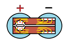
I have no concerns about being able to adequately bond the copper to nickel. I believe that if I just bond a simple copper strip over the entire nickel strip, then...when I go to spot-weld the combo onto the 18650's, the current will be able to pass through the copper from one spot-welding probe to the other (this is also why common nickel strips have a slot over each cell)...so I think the copper should have a full-length split down the middle.
I'm concerned about this because I believe it is important to get the copper as close as possible to the actual spot-welds, to reduce the distance the ebike operational current has to pass through nickel. Anyways, this is my initial idea. I thought I'd share for anyone who wanted to also experiment.


[one-mil is 0.001-inch thick, when researching sheet-metal options]
0.15mm__6-mil__34 ga [copper this thin will crumple like paper]
0.20mm__8-mil__32 ga
0.25mm__10-mil__30 ga [recommended for initial experiments]
0.33mm__13-mil__28 ga
[sizes below require sheet-metal shears to cut]
0.40mm__16-mil__26 ga__12-oz per sq foot/B370 architectural 99% copper sheet
0.51mm__20-mil__24 ga__16-oz
0.64mm__25-mil__22 ga__20-oz
0.81mm__32-mil__20 ga__24-oz
1.02mm__40-mil__18 ga__28-oz
Xxxxxxxxxxxxxxxxxxxxx
I have seen nickel-plated copper sheet on Makita, Metabo, Bosch, DeWalt, etc cordless tool batteries. This gives you the high conductivity of copper, with the easy to spot-weld nickel. It's possible to DIY plate nickel onto copper, but that experiment is for another thread. An idea popped into my head, and this is just a proposal.
I will attempt to use very high amps from an RSU (https://www.electricbike.com/resistance-soldering-unit/) to bond copper sheet over the common 0.20mm thick nickel strips. The 30Q can safely provide 15A per cell, and HG2 is rated for 30A, so 15A-30A is the goal without getting hot. If you simply double or triple the layers of 0.20 nickel, it will just get hot and have voltage sag. (not a theory, its been done several times with the same result)
I have no concerns about being able to adequately bond the copper to nickel. I believe that if I just bond a simple copper strip over the entire nickel strip, then...when I go to spot-weld the combo onto the 18650's, the current will be able to pass through the copper from one spot-welding probe to the other (this is also why common nickel strips have a slot over each cell)...so I think the copper should have a full-length split down the middle.
I'm concerned about this because I believe it is important to get the copper as close as possible to the actual spot-welds, to reduce the distance the ebike operational current has to pass through nickel. Anyways, this is my initial idea. I thought I'd share for anyone who wanted to also experiment.
[one-mil is 0.001-inch thick, when researching sheet-metal options]
0.15mm__6-mil__34 ga [copper this thin will crumple like paper]
0.20mm__8-mil__32 ga
0.25mm__10-mil__30 ga [recommended for initial experiments]
0.33mm__13-mil__28 ga
[sizes below require sheet-metal shears to cut]
0.40mm__16-mil__26 ga__12-oz per sq foot/B370 architectural 99% copper sheet
0.51mm__20-mil__24 ga__16-oz
0.64mm__25-mil__22 ga__20-oz
0.81mm__32-mil__20 ga__24-oz
1.02mm__40-mil__18 ga__28-oz