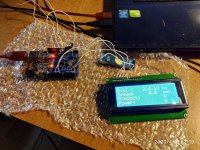
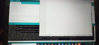
Completed DIY E-Bike Display with a JBD BMS

Joined
Oct 27, 2018
Messages
15
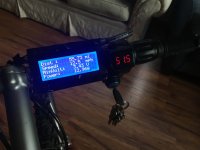
When looking for a BMS, I wanted to find one that could display pack data and power on a screen. I was so curious to see how much power my motor drew when riding along with my cell voltages. While there are BMS's out there that can do this, they are expensive and I found the JBD smart BMS and Simat's open source project on hacking into their communication protocol. Yes these are cheap Chinese BMS's, but this company seems to be pretty reputable and I haven't had any trouble. Anyways, thanks to the awesome work of Simat for explaining their UART communication protocol, I created an Arduino nano based system that reads data from the BMS and sends it to a 20x4 LCD screen.
IMG_5519.jpg
IMG_5395.jpg
If your BMS can be programmed with software that looks like this, then I believe it will be compatible with this project:
Screen Shot 2019-04-23 at 6.41.09 PM.jpg

System Specs:
Receives individual cell voltages and pack current from BMS
Measures bike speed using a hall effect sensor and magnet on the wheel
Save mileage data to local memory on Arduino
Prints out mileage, current speed, the voltage of the lowest cell and power draw on LCD Display

Here's a link to my GitHub where you can find information on how to do this yourself. This technically has everything you need to implement this yourself but Arduino programming experience would be helpful as I don't have a lot of documentation on what I did. Either way, this is a great project to learn Arduino programming, UART, LCD displays and PCB design. If there's interest, I would be happy to further support this project. There is plenty of room for improvement and this seems to be one of the cheapest and most hands-on methods for making an ebike display!

Please let me know what you all think :)

tl;dr: If you are looking for a BMS to buy or already have a JBDTools compatible BMS, consider gleaning from this open source project to make a nifty ebike display.
 
DjSpaceGhost said:
Is there something like this that is plug and play for dummies ? This is awesome.
Not that I know of. simat is the only other person I've seen develop hardware that can communicate with these BMS's and while he has a lot of documentation on what he has done, its far from plug in play. However, If you're interested in embedded systems, this would be a great project to start.
 
I've got a jbd bms too. The software is M$ only and quite buggy, but the bms seems to work. Mine is rated for 40A, but I only pump 25 through, so it barely gets warm. One thing I don't like is that the charge and discharge terminal are the same - seems to be prone to sparks when you plug in the charger. Overall I think it's an overkill. All I needed was a BMS that let you set up a lower charging + balancing tension to save battery life; the fancy monitoring is only useful during the design/test phase, where you need to have a close eye on everything. After that period, I'd only check for balance issues once a month, and so far there is none...
Interesting project though.
 
qwerkus said:
I've got a jbd bms too. The software is M$ only and quite buggy, but the bms seems to work. Mine is rated for 40A, but I only pump 25 through, so it barely gets warm. One thing I don't like is that the charge and discharge terminal are the same - seems to be prone to sparks when you plug in the charger. Overall I think it's an overkill. All I needed was a BMS that let you set up a lower charging + balancing tension to save battery life; the fancy monitoring is only useful during the design/test phase, where you need to have a close eye on everything. After that period, I'd only check for balance issues once a month, and so far there is none...
Interesting project though.

The XT90 anti spark connectors can help a bit but with high potential differences but yeah arcing is sometimes hard to avoid. I have to agree with you that the BMS is most important during design/testing. If you have good cells and treat them well, you should rarely have balancing needs. I'm a data freak and love to know how much power I'm drawing from the pack and the voltages of my cells as I'm riding, which was my main motivation for this project. Would be neat to implement a coulomb counting feature to get some sort of SOC or log energy usage over time.
 
That's great, thanks for posting. I can imagine someday having the BMS, controller and display unit all on a wireless network so they can interact but not need a giant hairball of wires.

If you plug the charger into the AC first you should not get sparks when you plug it into the pack.
 
fordtheriver said:
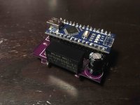
When looking for a BMS, I wanted to find one that could display pack data and power on a screen. I was so curious to see how much power my motor drew when riding along with my cell voltages. While there are BMS's out there that can do this, they are expensive and I found the JBD smart BMS and Simat's open source project on hacking into their communication protocol. Yes these are cheap Chinese BMS's, but this company seems to be pretty reputable and I haven't had any trouble. Anyways, thanks to the awesome work of Simat for explaining their UART communication protocol, I created an Arduino nano based system that reads data from the BMS and sends it to a 20x4 LCD screen.
IMG_5519.jpg
IMG_5395.jpg
If your BMS can be programmed with software that looks like this, then I believe it will be compatible with this project:
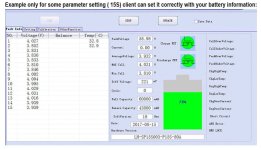
Screen Shot 2019-04-23 at 6.41.09 PM.jpg

System Specs:
Receives individual cell voltages and pack current from BMS
Measures bike speed using a hall effect sensor and magnet on the wheel
Save mileage data to local memory on Arduino
Prints out mileage, current speed, the voltage of the lowest cell and power draw on LCD Display

Here's a link to my GitHub where you can find information on how to do this yourself. This technically has everything you need to implement this yourself but Arduino programming experience would be helpful as I don't have a lot of documentation on what I did. Either way, this is a great project to learn Arduino programming, UART, LCD displays and PCB design. If there's interest, I would be happy to further support this project. There is plenty of room for improvement and this seems to be one of the cheapest and most hands-on methods for making an ebike display!

Please let me know what you all think :)

tl;dr: If you are looking for a BMS to buy or already have a JBDTools compatible BMS, consider gleaning from this open source project to make a nifty ebike display.

Your project is awesome. How difficult do you think is to add a state of charge bar? The BMS uses voltage to calculate it. I think that a Watt/hour counter will be extremely usefull too. The BMS does not count Watt/hour internally, so I think it should be calculated by constant polling the volts and amps reported by the BMS.
 
trazor said:
Your project is awesome. How difficult do you think is to add a state of charge bar? The BMS uses voltage to calculate it. I think that a Watt/hour counter will be extremely usefull too. The BMS does not count Watt/hour internally, so I think it should be calculated by constant polling the volts and amps reported by the BMS.

That seems feasible. I've just been watching my cell voltage for SOC but it would be nice to have the Arduino keep track of that for me. Since I'm already saving mileage to the EEPROM memory on the Arduino, it should be easy to calculate the current power draw, multiply it by my sampling time step to calculate the energy used during that time period, add that to the total energy used since the last charge, then save that to EEPROM (memory on Arduino).

The most difficult part of this would be creating the status bar on the LED screen. I'm imagining a simple bar graph on the far right side of the screen. To write characters to the LED screen over I2C, I use the wire.h and the LiquidCrystal_I2C.h libraries. These libraries do a lot of the heavy lifting so all I need to do is pass a string to a command and it will make those characters appear on the screen. Since the status bar is likely not a character supported by the LiquidCrystal_I2C.h library, I would have to modify that library to support the status bar. However, that seems like a pretty fun addition so I'm game! Will try to implement this in the next month or so, been very busy lately.
 
Hi fordtheriver

Thanks for taking the time to put this together neatly and clearly explained on GitHub and here!

I was researching the internet myself looking if this idea had been implemented already, and I found out through your post it did :D

I own one of these BMS on my Bafang BBS02 equipped ebike, and wanted to have a little more to display voltage and power consumption, namely watts per hour / mile.

Does your project read data from the BMS serial port or Bluetooth (which is actually connected to the same port?)
Also, didn't explore it enough to see where it is powered from?
Considering these Bafang controllers already have a speed sensor and wheel thing, do you think it could somehow be piggy backed on this?

Thanks so much
Regards
Pedro
 
Hi Pedro,

Excited to see your interest in this project!

1. This system communicates with the BMS directly via UART. It does not use Bluetooth. From what I've seen online, there is little documentation regarding communicating with the BMS over Bluetooth. As long as the system is grounded with the BMS, direct UART communication will work.

2. The current design uses a 36V-72V DC/DC converter to step down the battery voltage to 12V. See #5 on the git repository. There were three options I explored:
a. 5V pin from the UART port of the BMS. This is only designed to power the Bluetooth module, which wasn't enough to power the Arduino and the display. The Linear Voltage Regulator got very warm when powering the Arduino and the display and would have likely burnt up over time if I had used it (Big con) Don't have access to a 12V rail to power a headlight (big con).
b. Power the system directly off a 3s stack of cells via balance leads. This bypasses the protection of the BMS and unevenly discharges cells (big con).
c. Use a DC/DC converter to establish a 12V power rail from the battery pack. Placing this DC/DC converter after the BMS ensures that the system is protected by the BMS. (med win). A wide variety of converters can be selected based of power demands, i.e if you want a headlight/phone charging (big win). By using the entire battery voltage, the system evenly draws power from all cells (med win). However, this is a more expensive option (med con)
After exploring these 3 options I only recommend using option c.

3. I haven't used a BBS02 before, but if it comes with a hall effect sensor and a magnet, it is likely it can be used as the sensor input into this system. The sensor I used is powered with 5V and sends a high signal whenever a magnetic fields acts upon it. This triggers an interrupt in the firmware that measures how much time had passed since the previous signal. The link to the sensor I used is posted on bullet #5 on the git repository, so check out the spec sheet and see if it is interchangeable with the BBS02 one.
 
Hello friend, i was build your project, but have some problems with LCD refresh, when simulating the input of the speed sensor, there is no display of the result on the display,It seems that the program does not work in a loop.... Can you help me? :roll:
IMG_20200409_221925.jpg

Found errors in the sketch, now it works, thanks for a wonderful project
[youtube]1hT4_QCBnps[/youtube]
 
Thunder_blade said:
Found errors in the sketch, now it works, thanks for a wonderful project

Awesome to hear its working out for you and you're enjoying the project. It has been a long time since I've looked at my code so I was worried I wouldn't be of too much help. Good luck
 
fordtheriver said:
Thunder_blade said:
Found errors in the sketch, now it works, thanks for a wonderful project

Awesome to hear its working out for you and you're enjoying the project. It has been a long time since I've looked at my code so I was worried I wouldn't be of too much help. Good luck


I’ll try to finalize the project, adapting it for kilometers, since these values ​​are convenient for me and if you don’t mind, I can put the finalized sketch into the access. :bigthumb:
 
This is excellent job. I adopt it to may project, but still have problem. I have 17s Smart BMS to control 17S, 60 V, 20Ah Battery Pack. I want to get the data : Cell Voltage, Pack Voltage, Current, Temperature and Remaining Capacity (Ah) by Arduino Uno.
The adopting code and result is attached. The data is still not shown in arduino.
 

Attachments

  • E-Bike-Speedometer-and-BMS-Interface2.doc
    33 KB · Views: 156
  • WhatsApp Image 2020-10-15 at 10.11.00 AM.jpeg
    WhatsApp Image 2020-10-15 at 10.11.00 AM.jpeg
    72.4 KB · Views: 2,417
Great work fordtheriver, this looks perfect for me.

I'm going to try to buy a suitable BMS, can anyone confirm exactly what to look for? One sold by JBD that has "smart" and "UART" in the description?

I'm thinking of this: https://www.aliexpress.com/item/32793597854.html
(16s LiFePO4 battery)
 
Back
Top