Using the Wangdd22 1500W 30A DC Boost Converter on an ebike

Time to hot-rod the booster then. Once you extract the FETs, let us know what the part number is. Finding one with a lower Rds will usually reduce heating.

Also, once you remove or cut the gate leg, try measuring resistance (or diode check) from the gate drive to ground. Sometimes when the FET shorts, it blows out the gate driver which usually sucks to replace. If the gate drive to ground looks like a short, it's a bad sign. It should not look like an open circuit either. Often there is a gate resistor in series with the gate that will tend to act like a fuse when things blow up.
 
fechter said:
Time to hot-rod the booster then. Once you extract the FETs, let us know what the part number is. Finding one with a lower Rds will usually reduce heating.

Also, once you remove or cut the gate leg, try measuring resistance (or diode check) from the gate drive to ground. Sometimes when the FET shorts, it blows out the gate driver which usually sucks to replace. If the gate drive to ground looks like a short, it's a bad sign. It should not look like an open circuit either. Often there is a gate resistor in series with the gate that will tend to act like a fuse when things blow up.

Ummm ... I'll take a look at the circuit when I have time to focus and "decode" what you said above.

FWIW, this morning I removed the FET by cutting the legs and then de-soldered the PCB mount area using a de-soldering wick. While doing so, I noticed a small surface mount component labeled 1R0. Is that likely to be the gate resistor? Note: the FET is located on the other side. The three solder spots are for the FET.


Anyway, this is the MosFET as posted previously.
Wuxi NCE Power Semiconductor NCE85H21TC
http://www.ncepower.com/Upload/MOSFET/NCE85H21TCdatasheet-16543235225.pdf
(fixed the link)


wturber said:
I have no access to a scope.
You're welcome to borrow mine long enough to test stuff with. It's not great, just a tiny old portable that doesn't run off batteyr anymore (has to stay plugged in), but it's good for basic stuff.

I think I also have a bigger regular old scope but can't remember if it works correctly (I think so, not sure though).
 
Once you get the FET removed, measure ohms across the two outer holes of where the FET was. Measure both directions. If it measures anything that is not a short and not open, then it's a good sign.

The datasheet for the part says 85V, 3.9mOhm. It would be easy to find a better rated part in that package.
 
Using the Diode function of the meter:
Gate to ground: .9V
Drain to ground: 1.1V
Source to ground: .45 V

I used the negative power input terminal ground. Not sure if that was correct.

From Source to Gate res = 77.4 Kohm
From Gate to source res= 78.2 Kohm

Resistance across the small gate resistor was .5 ohm. It actually acted a bit like a capacitor, starting at 1 ohm and ramping down to .5 ohm. So it is nearly a dead short, but not quite.

Interesting side note on FETs and heat sinks. While fiddling with this I decided to finally replace the capacitor I blew when I mindlessly connected my 12VDC to 120VAC inverter to a 36 volts source (my bike batteries). I blew a capacitor and while I bought a replacement shortly afterwards, I never finished the repair. So since I was fiddling with the booster this morning I decided to finally repair it. While doing so, I noticed that its FETS were all attached to the heat sink by a clamping bar that sandwiched them against a gray silicon/fabric heat sink pad - a system much like my booster uses. Anyway that capacitor repair worked fine and the inverter is now working again (at least with a 20 watt or so load.)
 
amberwolf said:
wturber said:
I have no access to a scope.
You're welcome to borrow mine long enough to test stuff with. It's not great, just a tiny old portable that doesn't run off batteyr anymore (has to stay plugged in), but it's good for basic stuff.

I think I also have a bigger regular old scope but can't remember if it works correctly (I think so, not sure though).

OK. We'll see if I ever get to that bridge to cross. Thanks. :^)
 
fechter said:
Once you get the FET removed, measure ohms across the two outer holes of where the FET was. Measure both directions. If it measures anything that is not a short and not open, then it's a good sign.

The datasheet for the part says 85V, 3.9mOhm. It would be easy to find a better rated part in that package.

In my poking around I found few FETs that have a drain current as high as this part. My layperson brain assumes that this would be an important parameter to match.
 
Yes, the drain current should meet or exceed the stock part.
I took a quick look and you're right, there aren't that many that are better in that package size.
IRFP4468PBF looks like one. 100V, 2.2mOhm, 290A continuous drain current.


Your measurements look good. Always a chance the gate driver is blown anyway, but the measurements don't look like it.
 
fechter said:
Yes, the drain current should meet or exceed the stock part.
I took a quick look and you're right, there aren't that many that are better in that package size.
IRFP4468PBF looks like one. 100V, 2.2mOhm, 290A continuous drain current.


Your measurements look good. Always a chance the gate driver is blown anyway, but the measurements don't look like it.

OK. So in comparing the spec sheets I see the IR part has more capacitance and longer rise and fall times. Does that matter?
I looked up the price and it doesn't seem likely to be much cheaper than my options for a same part replacement. They all get pricey when bought one-at-a-time. Maybe if they have that IR part locally, it would be cheaper.

So my question is what are the potential advantages to using the different part? More reliability? More output power (If so, what else would to be changed?)

BTW, I'm encouraged by the decent test results and emboldened by my success repairing my inverter. So I'm probably going to follow through with this repair attempt even if it may not make a lot of sense financially.. Maybe I can improve the heat sinking and the sensing capability of the thermal sensor with better mounting. :^)
 
A better part would just give you increased reliability unless you did something else to the circuit. Maybe slightly less heat generation, but the stock part is not bad. The difference in gate capacitance will slow down the switching times. This may or may not make any difference. My guess is it won't.
 
fechter said:
A better part would just give you increased reliability unless you did something else to the circuit. Maybe slightly less heat generation, but the stock part is not bad. The difference in gate capacitance will slow down the switching times. This may or may not make any difference. My guess is it won't.

OK. So I checked the booster listing and it says that the booster operates at 150Khz. That means one cycle every 6666.66667 nanoseconds.

If I add the turn-on, rise, fall and turn on delay times for the IR MosFET, I get 702 nanoseconds. For the original part the total is 301 nanoseconds. I'm not sure if it is appropriate or not to compare these times to the cycle rate, but it seems a sensible assumption to me that even the slower, non-OEM MosFET could operate at over 1 Mhz. Given the small difference in prices between the two choices, and the still lingering question of compatibility, I'll probably flip a coin tomorrow and go with the results from that.

I swung by Frys electronics today hoping that they would at least have the capacitors, but they did not. They did, however, have 5K trim pots in packs of two for $3. So I bought a pack and checked their maximum resistances. One measured 4.78 kohm while the other was 5.14 kohm. So I got lucky. If I can get the old booster working again, I'll swap the > 5K ohm trim resistor into the new booster and see if that will allow that booster to operate at its spec. I don't want to swap it right now and risk having no booster.
 
Did more research and decided to stick with using the stock replacement MosFET. That the stock item is faster (rise fall) led me to be concerned that the replacement part might be a tiny bit less efficient. The smallest number I could order on ebay was five and other sources charged a significant premium for ordering just 1 or 2. So I expect to have three extras since I'll keep at least one for an additional spare. So if any of the guys who pitched in with advice here has a use for one or two of these, just let me know and I'll snail mail one or two to you when I get them.

I haven't ordered replacement capacitors yet. I was thinking about installing the MosFET first since it is known bad and seeing if that gets the booster going at low to medium power. If it does, I'll replace the output capacitors before running high power. If the new MosFET does not fix it, I'll probably just scrap it on the assumption that there are some parts other than the MosFET and capacitors that have failed and won't be worth the time to track down.
 
Sticking with the stock part is probably the best plan.

You are correct that the switching speed might make a difference. In real life, the actual switching speed depends a lot on the gate driver and we don't really know what that is or how it would behave. For sure the part I was looking at will be slower than the stock part.
 
Alan B said:
I squared R losses almost certainly exceed switching losses.
Mostly over my head. But I think you are saying that any loss of speed in the switching would be of little consequence. Perhaps so. But it was hard to see the any clear benefit from the other options I could find.

Alan B said:
They buy "barely good enough" FETs, the cheapest they can get (often counterfeit). So you can assume whatever they've chosen is barely adequate.

I've been told I could assume a lot of things about this booster - many of which have so far turned out to false. Besides that, it was hard to find other FETs that met the published specs of this particular one. This converter did deliver on the claimed efficiency and never appeared to run hot - even in Phoenix. Further, it over-performed slightly on the specified current output. So I give the folks who made it some credit for making a product that performed as advertised. I'm only slightly less satisfied with the replacement unit.

Also, the output capacitors were high quality Japanese capacitors. Of course, perhaps those are fake and are really sub-par? OTOH, the FET is marked NCE. I don't think that is a premium supplier ... and they didn't bother to fake a better brand there.

Either way, it's all academic now and this repair is as much a matter of a "for fun" exercise as anything else. I have the replacement FETs of the same type as the original (http://www.ncepower.com/en/proshow.aspx?cateid=97&productsid=3491). They are presumably authentic - but who really knows. I'll solder one in and see if the booster comes back to life or not. If it does, I'll replace the three output capacitors with presumably authentic copies based on Amberwolf's recommendation since one of them has a slightly bulged dome which apparently makes them all suspect. If the booster doesn't revive, no big deal. I've learned a little bit about these things in the exercise.
 
Your new FETs may be more authentic than the ones that were already there. Compare them closely, the fakes usually have signs of copying. Comparing side by side to the real thing is often revealing, especially with an inspection microscope (low power stereo). Of course not everything is fake.

We had products made in China for some projects and they COULD NOT BUY authentic pure copper wire or quality nuts and bolts. Their supply channel is just polluted with it. We had to send any critical parts or materials direct from USA to their facility. We had to reject a lot of faulty wire. It must have had something alloyed in with the copper (possibly recycled material), not sure what, but it did not meet the resistance specs of pure copper that it needed to. This was large gauge square wire with an internal water cooling channel in a critical application, so we noticed.

We had large batches of Dell computers that died due to bad electrolytics. We had Cisco network gear with bad parts that somehow leaked into the supply chain. It is not every part, but anything very costly is a good target to make some money. If you are going to fake a part, it would be more profitable to mark it higher quality (like from Japan), so the caps may be more profitable to fake than the FETs, and harder to know they are fake (more subtle problems caused by missing some specs). The design is also likely marginal so the caps are stressed, and you live in a very warm environment which itself is hard on caps and shortens their lifespan. So it may be the caps are real but the design is pushing them too hard. Caps can not handle much ripple current, and understanding those aspects of the design are somewhat subtle.

Good luck with your repair.
 
Slightly OT, but:

The worst problem with capacitors doesn't even require they be counterfeit. If you look up "Capacitor Plague" there's plenty of explanation about the details, but essentially it comes down to problems with the formulation and manufacture of the electrolyte itself.

Going cheaper on that may mean it has a lower boiling point, or that it's chemical structure allows outgassing from electrolisys, etc. Either of those causes early failure of the caps, and even earlier when exposed to heat or conditions causing high ripple currents. Affects the capacitor's various specs, too, but the main issue is that as the electrolyte fails, it lessens the capacitance and increases the resistance, which means the cap doesn't do the job it is there to do as well, and eventually at all.

Sometiems they actually explode from the outgassing, usually once they reach some critical point where the extra resistance and higher ripple causing higher heating cuases more electrlyte loss causing more heat and so on.

(Sometimes they explode because poor QC of the boards they're in doesn't find that they were put in backwards. ;) But that will happen wiht *any* cap regardless of how good it is. :/ )


I've seen batches of even really good cap brands have bad electrolyte; where they all just fail with the swelling, or just plain venting / exploding.

After the problem first started, early this century I think, it was hard to be sure you'd get good caps, because even when manufacturers recalled their production, and recycled them, whoever was supposed to do taht didn't, and instead resold them back into the parts supply line.... I expect even now this still occurs, with everything from batteries to caps to FETs to every possible type of component. Instead of being recycled for raw materials, bad batches of parts instead simply get resold as new stuff via other supply channels. And it causes no end of grief to end users and companies trying to use and build quality stuff, because just about every facet of the parts supply chain is "infected" with these bad batches of everything imaginable. :(
 
Alan B said:
Your new FETs may be more authentic than the ones that were already there. Compare them closely, the fakes usually have signs of copying. Comparing side by side to the real thing is often revealing, especially with an inspection microscope (low power stereo). Of course not everything is fake.

So I compared the original FET to the new ones and if I had to bet, I'd bet fairly heavily that the new ones are counterfeit.
Five reasons.
1) The logo isn't a good representation of the NCE logo. (Examined with 8x loupe.) The "N" appears to be integrated into the oval while it extends outside the oval on the real logo and on copies found on other samples of different NCE parts I've looked at online.I may post an image.
2) The printing is uneven and not very deep compared to the removed part.
3) The "smooth" dot depressions on the top of the case aren't really smooth. They have a brushed texture.
4) The back plate is slightly different and its shape doesn't have the same level of detail and fineness
5) Some claims that the seller I bought them from has sometimes supplied counterfeit components. The upshot is that they are a broker and don't necessarily vet all sources well. Their ebay rating is 99.5% with LOTs of transactions. But that doesn't mean that some percentage of what they sell isn't actually counterfeit.

Of course, I don't really know one way or the other. In one online comparison the nicer and more professional looking package was actually the fake one. I'm glad this repair isn't particularly important to me. ;^)

Alan B said:
Good luck with your repair.

I will apparently needs some of that.
 
I see you ordered your replacement FETs on eBae. Counterfeits are rampant there. At least you can probably get your funds back easily. You may want to make some good photos of the parts for that.

eBae is Not a proper source. You may indeed need some good fortune. Hopefully they will at least work, but they may fall short of meeting spec. Perhaps it will function at least momentarily. :)
 
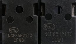
Here's a pic comparing the Ebay FET to the original. Notice how the NCE logo is wrong in so many ways. The "E" is oversized. The N is shaped wrong and the three lines are connected, not separated as three segments. The oval isn't really a nice oval. It terminates on the leg of the "N" when it should terminate in the space between the N's left vertical line and the "V" on the right. In short, it is a very poor imitation of the NCE logo. Note also that the three presumably legit components have thicker and deeper etchings of the logo and text.

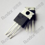
I'm including a picture from the internet of another couple NCE components for comparison as well. The ebay FET looks phony as heck to me. I'm assuming that semiconductor manufacturers care about their logos much like most other company's and would not put out products with such obviously incorrect renditions of it.

I was thinking about soldering one of these into the defective booster just to see if it would work. But I really don't want it to work and then fail again because of a junk replacement. So instead, I'll probably send a note to the supplier today with these photos and explain to them that I think they sent me counterfeits and see what they have to say. In the meantime I'm looking for replacements from a better supplier. But given that these are Chinese FETs, that isn't so easy.


Ebay_FET.jpg
View attachment 1
NCE30H12-30V-120A-low-resistance-N-channel-MOS-transistor-Mosfet.jpg_640x640.jpg
 
While I'm trying to sort out the apparent bogus FET situation, I've been working on making this bike more of a functional commuter and a semi car replacement.

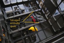
I added a milk crate a few weeks ago, but the one I have isn't particularly rigid and bends while hanging on the back of the rack. I'm not sure where to get a "real one." This one was $6 from Target I think. So I strapped in two hollow aluminum bars to the bottom that I salvaged from a broke patio umbrella. No more sag. We'll see how they hold up.

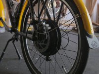
Next up was to change the 160 mm rear disc to 180 mm in the hopes that it would provide better clearance between the brake caliper and the rear hub motor. I only have a couple millimeters depending on how it is adjusted. Unfortunately it didn't help as much as I had hoped. I think I have to move to 203 mm.

We are currently in the middle of our monsoon (rainy) season and I've had to ride in the wet and rain a couple times. This is very strange for a native of the area since we can go many months without rain. So I've coated most of the electronics boards on the bike with conformal coating and have enclosed the booster in some semi-clear plastic sheets. But the back tire is still splashing the controller under the rack and the front tire is splashing both me and the booster. Time for fenders. These were on sale for about $20 at a local Performance Bicycle shop. But they were black and I was getting bored with everything being black. So I spent last week layering on about five or six coats of orange-ish yellow paint (a couple coats each morning) to make sure the black was well covered and then topped it off with some clear for a bit more durability (and shine). I had to get creative with the attachment points and I'm not sure if the front fender is low enough. It should probably be lower.


ReinforcedCrate_P1400027.jpg
180mm_P1400029.jpg
View attachment 2
 
wturber said:
I added a milk crate a few weeks ago, but the one I have isn't particularly rigid and bends while hanging on the back of the rack. I'm not sure where to get a "real one."
Well, the *real* real ones are illegal for individuals to posess, because they are owned by the beverage/etc companies whose logo is on them, and usually have the legal references embossed into their plastics indicating the fines for having them in your posession. :/

There *are* heavy duty crates made the same way, available for sale, but I haven't ever seen any locally--just on the web. ULINE makes some. But all the ones that actually turned out to be made as well as the "real" ones were in the $30-$70 range, each, last time I looked.

That's one reason I went with the metal-box approach on DayGlo Avenger (and that I could add a lid and lock them), when I made panniers.

It's easier to find wooden ammo crates, or even to make a lightweight wooden crate of your own, even with a lockable lid, than to find affordable durable plastic crates.


If you keep an eye out at estate sales or other places where much older stuff might be found, you sometimes run across the very old metal wire versions of the crates. While these are probably also covered under the laws, there's nothing actually on them about that, and usually no owner's logos/names/etc on them either.

So I spent last week layering on about five or six coats of orange-ish yellow paint (a couple coats each morning) to make sure the black was well covered and then topped it off with some clear for a bit more durability (and shine).

FWIW, Krylon white primer (and probably most others) would cover the black right up, and help the color paint stick well. :)
 
I've seen guys that put a piece of plywood or Lexan in the bottom of the plastic crate to stiffen it up. Maybe under the bottom in your case.
 
Back
Top