Icewrench
10 kW
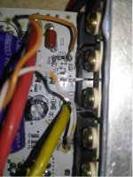
BH or brake high would connect to the pos voltage line to a brake light.
Bl Brake low is a ground signal..
Bl Brake low is a ground signal..
Icewrench said:BH or brake high would connect to the pos voltage line to a brake light.
Bl Brake low is a ground signal..
amberwolf said:What votlage does the battery dip down to under the load?
What is the controller's LVC?
If the battery dips below the LVC, and the LVC is correct for a 20s or lower pack, then it is still the battery being unable to handle the load, even though the controller is shutting down because of it.
If the battery does not dip below the LVC, then the controller is shutting down for some ohter reason.
If the LVC is set higher than a 20s pack, then the controller is shutting down early when the pack dips below that point under load, and the controller needs it's LVC changed to match the pack being used.
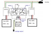
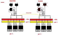
PITMIX said:hello, do you have the schematic of the motherboard?
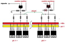
I want to know how to control the power mosfet.
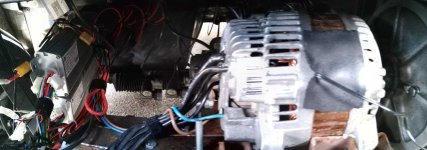
PITMIX said:it is a alternator of Renault Laguna 14V 210A converted into a brushless motor
PITMIX said:Hello when you connect learning wire your motor is running ?