INFINEON CONTROLLERS FOR DUMMIES

Read as much as I can and i still can't get a smooth throttle response.

I guess there are lot more of us DUMMIES out there than I thought!

Anybody out there really have stock settings? I got a set from Keywin, but there is no way it's what he sent.

Before flashing it the 3 speed switch had 3 speeds but he says they are set at 100% in all positions. Also the current was 30a and the phase only 78. this was for the 12fet 72v 1500w unit.
the 6 fet shows 18a batt and phase at 47a. All speed switch was at 100% in all positions.

On the same subject but differant problem is, I get a roughness or like a missfire from 10mph to 14mph. If I change the amps it changes where the missfire is.

other is if I hit the throttle to full too fast it cuts out but will go if I return the throttle and reopen the throttle. It is more r5egular on the 100% & 120% positions. In all 3 switch positions if I open the trottle slowly it works hust fine.

So after all of that where or what is really the proper settings and WHAT IS BLOCK TIME?

If I lower the battery current and up the Phase the misfire or roughness rises and if I lower the phase and up the battery it lowers the misfire. i got it pretty close on my other Mac 8t, but I don't remember what I set it at.

So does anybobdy really know what TIME IT IS? SETTINGS IS WHAT I AM ASKING.

Setup is 15s lipo EB312 irfb4110's into a Mac 8t on a 26" wheel. I also noticed the differance in throttle sensitivity, one was very coarse and another is much smoother. Why would that be if they are all HALL controlled?

So what should the ratio from battery to phase current be?

Dan
 
Hi
The settings keywin uses to start with are just an example he is not actually a ebike rider as far as I know he may have taken up the hobby but if he has he sets the controllers for the china market.
You have a 15s lipo setup that is just over 60 v fresh off the charger, with that type of battery pack the current draw capable is very high and believe me from stationary going straight to full throttle will draw a very high current dropping quickly as you get up to cruising speed, a cycle analyst will show you what sort of thing I am talking about.
The sort of settings to use when you program the controller is as follows:-
Set the current values to there maximum setting
Low voltage set to 45v or as close to as possable if you have a seperate LVC device this is not so vital the next one
The next setting is tolerance though depending on the software it may have a diferent name, it controls the time you can be over the limit settings before the controller cuts power set it to maximum
EBS voltage is maximum voltage regen will work at set to 75 ( only used with DD motors)
Block time never did pin down what that ment I set it to 4 normally
Auto cruse time this is used to allow you to activate the infineon's cruise control system automatically, there 2 ways to activate cruise control the normal way is to set the throttle to a speed you want then press the cruise controll switch if you have one fitted the other is to permanently have the cruise control switch closed then you set the auto cruise to say 8 then hold the throttle steady for 8 seconds then let go and the controller will activate cruise control. If using this then keep the numbers high
Slip charge indicate. Set to only fake indicate
EBS. Set to 2 if you want regen with no regen 0 is best
The speed mode section is up to you but set indicate mode to 1: comm GND
Converse speed is reverse ( only works with DD motors)
Speed is done in percentages not MPH or KPH choosing the settings by trial and error

The rest of the settings can be set as you want it is unlikely you have the means to use them

I hope this helps you
Geoff
 
Thanks Geoff,

appreciate you info.

If I go to the max power it will blow the clutch on nthe Mac.
Been there done that and it wasn't max amps.

I get all the cruise and the rest of the useless items but am still looking for a battery amp setting to phase setting that is useable. Some say 2.5 times battery fo the phase some 2.3. I have been up and down but wish there was a way to get what you have set it after all the changes. As I don't save evey change and don't remember exactly what I set it to.

I have tried the "stock" settings as Keywin said they were, not a chance was it what they were.

Somebody has a favorite setting that seems to work on a Mac 8t.

I like power but not too much that blows the clutch. I don't understand why I get the misfire or roughness between 10 to 15mph or higher as I change the power ratios.

I have seen 75+ amps on my CA SA but not with the 12 fet controller only my 6 fet one. The 6 fet seems to have a setting that works well and I can't find it on the 12 fet. I even tried those settings and it still has the missfire as I call it.

Which is more important the battery current or the Ohase? If I lower the phase and up the battery what does that do? And then the other way, high Phase lower battery.

So really as I put it before, "WHAT IS STOCK SETTING FROM kEYWIN OR LYEN?

Dan
 
Hi
Not actually come across a MAC motor so I don't know the parameters for it, most motors can take high amps for short times that's why I said use max settings, you will have to come at it from the other direction start low and go higher.
Set the tolerance to its lowest value, set the rated current to what you used and had the motor cut on you, set the phase to about 2 to 2.5 times the rated current. The only way is to test then up the current and test again, up the rated current by 5 amps each time altering the phase current to match. When you have found a setting that does not cause the motor to stall on full throttle from stationary take the rated current down by 5 amps and increase the tolerance till there is no stalling.

As for the glitch at 10 to 15 mph I can't help you there.
Geoff
 
The MCUs in these infineon controllers all appear to be 8051 based, which means they all likely share the same code base. Would be interesting to see if we can read the firmware off of these chips to modify the assembly. Does anyone know for sure if these chips are being cloned? If there are proper clones then that means the code is probably for sale somewhere.

What is the history behind the various e-bike controllers we're using, were they originally being manufactured for a specific bike/company?

I'm wondering if it would be difficult to get the original code for these controllers so we can improve their handling and add features. Infineon have published some documentation, code, and development kits for the MCUs in some of these controllers:

http://www.infineon.com/cms/en/product/microcontrollers/8051-compatible-8-bit-microcontrollers/channel.html?channel=ff80808112ab681d0112ab6b7661083f

Could be a start for an open source firmware.
 
a noob question here :)

I got 18fet cellman infineon, but right now I don't have batterys to test it yet. All I have is a lead battery.
is it ok to put battery low voltage down to 10v and run it on that for testing purposes (connecting wires, ..)
 
Also you will most likely need to reprogram the lvc and bypass the drop-down resistors.

If you have an all in one printer or other electronic device around the house, they often utilize power supplies with voltages above 20V. They would work for bench top testing.

Not ideal and could be dangerous, but you could try 5 to 7 9V batteries hooked up in series for no load testing. Make sure to monitor battery temp and don't add a load.


gwhy! said:
I dont think the controller will work with anything lower than around 20v
 
Good morning,

This dummy want too knows where the shortcuts on the pcb stands for.......

DS=
E=
S=
B=
1:1=
GND= Ground
XS=Speed limiter
T-,T+,T= throttle
-,W,V,V,+= Hall signal wires
RY=
VS=
RL=
D=
Q=
XL=
X=
XL,X=
+= Battery +
-= Battery -
 
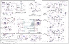
Hello, I have been studying the many useful posts in this forum for the past month or so trying to find good programming information for the Chinese e-bike controllers I recently purchased (seem to be Sunwin or a clone of Sunwin...) with a gpm8f3116 processor and a different programming connector than the Infieon (marked "jtag" on the board) with connections going to GND, SDA, SCK and +5 on the processor so it is not going to be as easy as the Infineon boards to figure out. But in the process of reading the existing 11 pages of "INFINEON CONTROLLERS FOR DUMMIES" I have seen where there is a lack of great documentation on the XC846 processor, so I would like to upload this xc846 based controller schematic I found just last night for those who might glean just a little more useful information on the processor and a complete schematic using it. Descriptions are in Chinese, but someone may be able to translate it and make it more useful.

dspanz
 

Attachments

  • xc846_circuit2.jpg
    xc846_circuit2.jpg
    297.6 KB · Views: 3,082
For an Infineon 12 FET IRFB 3077 controller, has anyone gone above 40A battery and/or 112A Phase current and had their controller survive without any problems?

The 40/112 settings are what EM3ev uses and the max they recommend. I am not an electronics expert but IMO the controller should be capable of a little more, I am just not sure how much more :D .

Thanks for any actual experience :wink: .
 
I've found the 12 fet 3077 incredibly robust and programmed it to 100A battery and 250a phase, running a Cromotor v1 and then a MXUS 3k on a 14s, and used it in slow speed, high load conditions riding up 30% rock covered hill sides.

I'm sure you'll be fine bumping up the power a bit.
 
I just received this controller:
https://www.aliexpress.com/item/32959235022.html?spm=a2g0s.9042311.0.0.3f2c4c4d88vie5

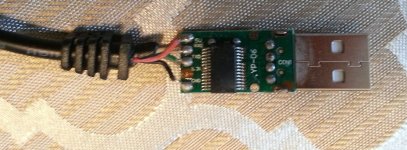
I used a programming cable that works fine on another KH6XX controller but it doesn't work with this new controller. I am using XPD 0.4.1 and trying to read setting from the controller. Is this controller not programmable? Does the pin-out to the USB-to-Serial cable look correct?

Here is what it it says on the board:
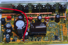
IMG_20200901_141129.jpg

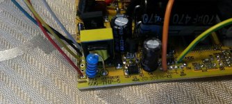
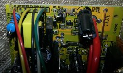
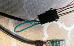
I have attached a programming lead to the board as follows:
IMG_20200901_141000.jpg
IMG_20200901_141058.jpg
IMG_20200901_141052.jpg

If the photos don't show it well here is what I've done:
controller +5V = Red -> 5V on USB
controller SDA = Yellow -> Jumps to TXD (green)
controller GND = Black -> GND on USB
controller RXD = White -> RXD on USB
controller TXD = Green -> TXD on USB
 
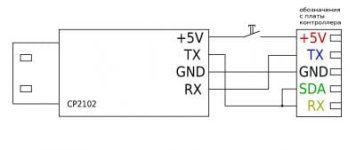
I manged to find the answer. Here is a USB programming wire diagram for Infineon 4 (KH6XX) controllers:
vrrxt9_thumb.jpeg

Found it on: https://electrotransport.ru/ussr/index.php?topic=13277.msg892795#msg892795

I just had to swap the RX and TX wires on the controller end and I was able to program my controller with XPD. I am not using a switch on the +5V.
 
Hi,

I'm using W806, which is based on Infineon 4 chip and maybe correlated to KH6xx?!. Does anyone here has experience with motors with high gear ratio like 1:8 - 1:12? I have some issues with the controller when releasing the throttle while driving. The motor is kind of shaking or jitter. These controllers do a FOC but looks like this is not working on every motor smooth. I have another motor also geared on 1:5 ration that is working okay. Also I have recognized that as soon the wheel is slip through it seams like the controller is reducing rpm.

Any ideas always welcome :)
1687946858488.png
 
Not sure I understand the issue. It behaves strange when you let off the throttle? Does it have regen braking?
 
Back
Top