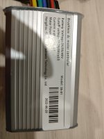
I bought a new LED Display and a new controller.
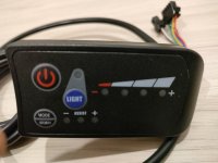
When I connected my new LED Display with my NEW controller, the LED did not power up. See attached photos.
To narrow down the problem, I did the following:-
1) I connected my NEW LED Display with my OLD controller, it didn’t powered up too,
2) I then connected my OLD LCD Display with me NEW controller, it powered up, but when I turned the pedal, the motor did not turn,
3) I then connected my OLD LCD Display with my OLD controller, the same old problem came back, the motor will cut off intermittently and then came back and this problem repeated itself.
4) In order to be sure that the PAS is not the problem, I measured the PAS voltage as I turned the pedal, it was between 2.8 to 2.9 V, quite consistent, even when the motor cut off, the PAS was at 2.8 to 2.9 V. Can I conclude from here that there is no problem with my PAS?
I suspected that the reason for the NEW LED Display not powering up is because I connected the wires wrongly.
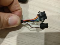
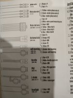
From the LED side, it has red (positive), blue (electric door lock, what is this?), black (negative), green (data receive) and yellow (data transmit). See attached photo.
From the controller side, it has red (positive), orange (VCC, what is this?), black (ground), green (data transmit) and yellow (data receive). See attached photo.
Is it correct to connect the blue (electric door lock) to the orange wire (VCC)?
Anyone can advise me what I should do next?
Thank You.