There are lots of solid state relays on the market, but most of them only work with AC loads since they use SCRs or Triacs.
SSRs made for DC loads are quite expensive for some reason.

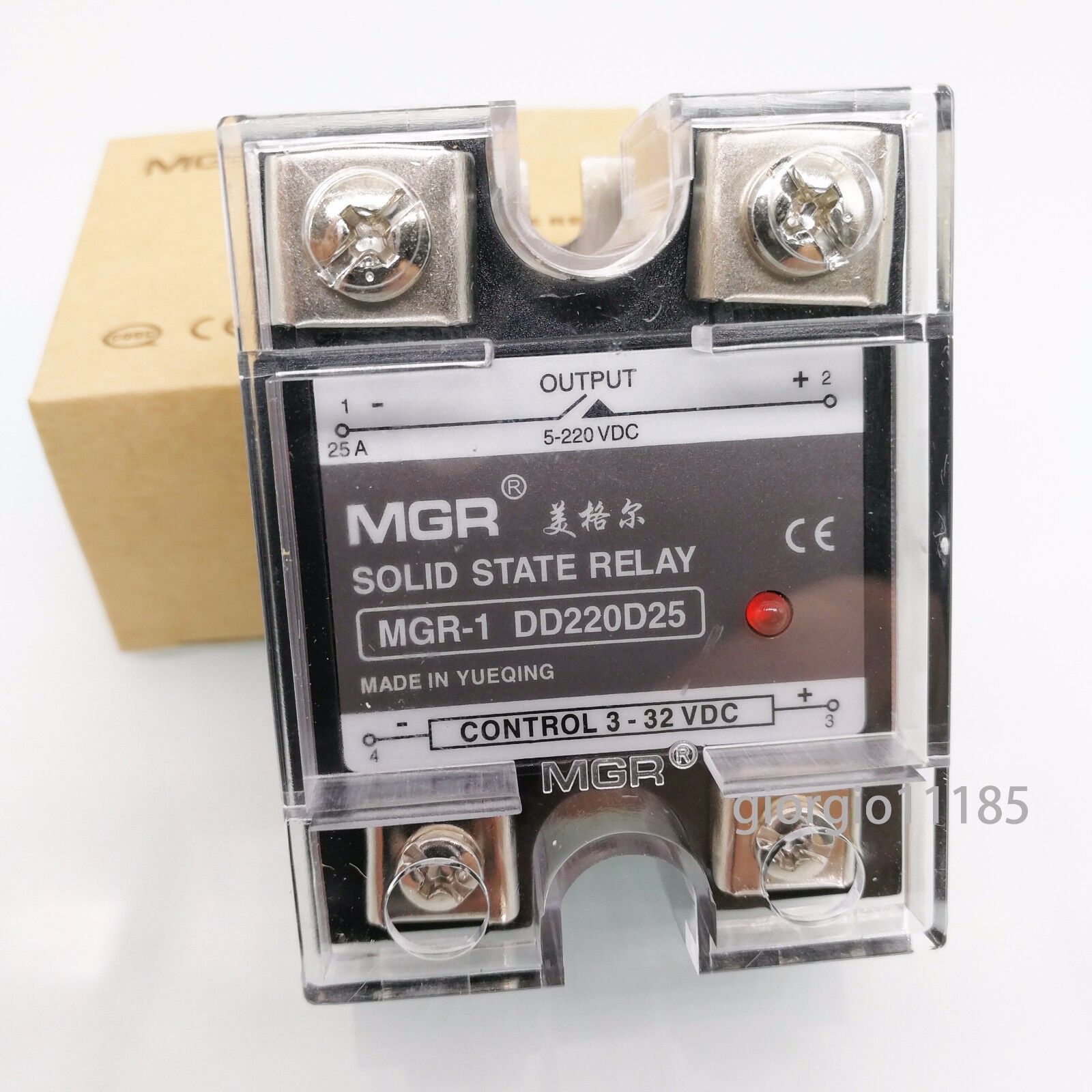
The cheapest ones are around $50usd and many are over $100. Being cheap, I found a way to make my own for quite a bit less and there are several options for the build. These are handy for lots of things and can be used on the positive side of the system just as easily as the negative side. Things like dc-dc converters, lights, horns can all be switched from pack voltage. The input can be driven off the 5v line coming from a throttle or sensor with the right resistor. This allows for using small switches and wires on the handlebars to switch fairly large loads.
The heart of it is an opto coupler with a photovoltaic output. Basically a LED shining on a micro sized solar panel. The good ones also have a circuit that will speed up the turn off. The output of the opto coupler can drive the gate of a FET (or bank of FETs) directly.
I tried a couple different optocouplers and they both work pretty well.
One is a ASSR-V621 which is a dual with 7v output @15uA.
The other was a FDA217, which has a 12v output @ 9uA.
They make single channel chips, but the dual channel ones are about the same price, so why not. With a 2 channel, the channels can be combined to get faster switching speeds or to switch two FETs that are back to back for bidirectional loads.
There are many options in how these can be used. Below is a simple single channel setup for a unidirectional DC load.

I used a CL2 current limiter chip on the input to keep the emitters at 20mA over a wide voltage range. You could just use a simple resistor if the input voltage is constant. I also show a diode to protect against reverse polarity. This is optional. On my prototype I used a red LED in place of the diode as an indicator.
For bidirectional DC loads, use two FETs back to back with the source pins in parallel.

I build one on a piece of perforated board for testing.

This one is using a single IRFB4110 as the FET since I had a bunch lying around. At 20A load, the heat dissipation will be at about the limit for this package without a heat sink. Adding a heat sink would allow for higher load currents. Parallel FETs could also be used, but will have slower switching times.
With the single 4110 FET, I measured the turn-on time to be about 1.5mS, which is pretty slow. Turn-off time is much faster, about 50uS due to the turn-off circuitry inside the opto coupler. What this means is you can't use it for high speed switching.
I did some bench testing with a power supply to see if I could blow it up, but it was able to take everything I tried (up to 5A @ 35v). I'll have to try it at higher voltages and loads.
If it all tests out OK, I plan to pot it in epoxy like the expensive boys.
SSRs made for DC loads are quite expensive for some reason.
The cheapest ones are around $50usd and many are over $100. Being cheap, I found a way to make my own for quite a bit less and there are several options for the build. These are handy for lots of things and can be used on the positive side of the system just as easily as the negative side. Things like dc-dc converters, lights, horns can all be switched from pack voltage. The input can be driven off the 5v line coming from a throttle or sensor with the right resistor. This allows for using small switches and wires on the handlebars to switch fairly large loads.
The heart of it is an opto coupler with a photovoltaic output. Basically a LED shining on a micro sized solar panel. The good ones also have a circuit that will speed up the turn off. The output of the opto coupler can drive the gate of a FET (or bank of FETs) directly.
I tried a couple different optocouplers and they both work pretty well.
One is a ASSR-V621 which is a dual with 7v output @15uA.
The other was a FDA217, which has a 12v output @ 9uA.
They make single channel chips, but the dual channel ones are about the same price, so why not. With a 2 channel, the channels can be combined to get faster switching speeds or to switch two FETs that are back to back for bidirectional loads.
There are many options in how these can be used. Below is a simple single channel setup for a unidirectional DC load.
I used a CL2 current limiter chip on the input to keep the emitters at 20mA over a wide voltage range. You could just use a simple resistor if the input voltage is constant. I also show a diode to protect against reverse polarity. This is optional. On my prototype I used a red LED in place of the diode as an indicator.
For bidirectional DC loads, use two FETs back to back with the source pins in parallel.
I build one on a piece of perforated board for testing.
This one is using a single IRFB4110 as the FET since I had a bunch lying around. At 20A load, the heat dissipation will be at about the limit for this package without a heat sink. Adding a heat sink would allow for higher load currents. Parallel FETs could also be used, but will have slower switching times.
With the single 4110 FET, I measured the turn-on time to be about 1.5mS, which is pretty slow. Turn-off time is much faster, about 50uS due to the turn-off circuitry inside the opto coupler. What this means is you can't use it for high speed switching.
I did some bench testing with a power supply to see if I could blow it up, but it was able to take everything I tried (up to 5A @ 35v). I'll have to try it at higher voltages and loads.
If it all tests out OK, I plan to pot it in epoxy like the expensive boys.