2 Large, identical battery packs in series? POSSIBLE?

d0pamine

10 µW
Joined
Feb 5, 2020
Messages
5
Location
LA/OC border
Hey all!

Here's my quandary:

I had a battery pack made from a legit china supplier for my first ebike build.
The battery pack is still relatively new and has the following specs:

52V 20AH 30a BMS

If I have another identical battery made by the same company would it be possible to connect them together in series with a connector like the one below?
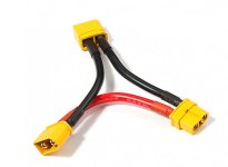
series-harness.jpg

If possible what would be the resulting output 104V 20AH XXa discharge ?

Is there a stock controller model i.e. sabvoton kelly etc that could handle 104V fully charged?

Worth mentioning is I'm trying my best to utilize the battery pack already made instead of paying nearly double for new pack with less than double the power (based on supplier quotes) to build a higher power bike project.
I don't think it would be worth taking the battery pack apart and rewiring 2 packs if that is the only way.

Any advice would be extremely appreciated! Let me know what you think
 
It is possible to connect two identical packs in series. They key is that they must be the same capacity and have similar internal resistance so that they are discharged at the same rate. That can be tricky even with two similar packs.

I would recommend running the packs in parallel instead unless you need more rpms. Adding the packs in parallel will still let you double the power. It will double the max discharge current. So instead of 104V @ 30A you could do 52V @ 60A for instance. This also allows you to use less expensive and more common 52V controllers. The critical thing with parallel packs however, is that they must be at the exact same voltage before connecting them together (approximately 0.1V or less).
 
Do the packs have BMSs?

Most MOSFETS are already right at their stress limits in the 90's, going for reliable components comfortable over 100V is a big jump in cost.

With cheaper gear I'd stick to 94V, so 22-23S
 
pwd said:
It is possible to connect two identical packs in series. They key is that they must be the same capacity and have similar internal resistance so that they are discharged at the same rate. That can be tricky even with two similar packs.
Just a note - if you have two of the same type packs in series you get an automatic guarantee that they are discharged at the same rate. Internal resistance doesn't matter.
 
billvon said:
pwd said:
It is possible to connect two identical packs in series. They key is that they must be the same capacity and have similar internal resistance so that they are discharged at the same rate. That can be tricky even with two similar packs.
Just a note - if you have two of the same type packs in series you get an automatic guarantee that they are discharged at the same rate. Internal resistance doesn't matter.

I guess you mean if you have 2 packs in parallel?
 
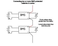
If the packs have a BMS and one trips during discharge, the full voltage of both will be across the FETs and may cause failure. This can be prevented by placing a large diode across each pack (reverse biased) so when one trips, the diode conducts and keeps the voltage on the BMS within the design limit.
 
Thank you greatly everyone for your feedback/knowledge!

It sounds too me like there really isn't a stock controller that could reliably handle this voltage (in series) even if all the conditions of the 2 packs were perfectly ideal/balanced ?

I was looking to crank out somewhere in the ballpark of ~6000 watts which is why parallel didn't seem to make sense for the project.

It might be a different subject but for some reason my battery pack supplier claims that a BMS with anything over 60a would be "expensive" and take much longer than usual to assemble. Of course this is all entirely based on the vendor I found with the best quality/price ratio, i definitely am not implying this is the consensus among all builders and manufacturers.

Theoretically if I want a pack that is capable of 100a-150a "burst" (meaning not this high continuously until the pack is as dead as a door knob); is/can "capable" and "continuous" amp discharge on a BMS be different?
 
j bjork said:
I guess you mean if you have 2 packs in parallel?
No, series. When they are in series, whatever discharge current one sees, the other will see. By definition.

Two batteries in series will see exactly the same current - but voltage will not be forced to be the same. Two batteries in parallel will see exactly the same voltage - but current will not be forced to be the same.
 
d0pamine said:
It sounds too me like there really isn't a stock controller that could reliably handle this voltage (in series)
there's a lot of them. just not cheap ones. you just have to get one that can handle the full charge voltage, which is nearly 120v.

there's some here on es in the for sale section, among others. sorry i don't have a link to the threads.


I was looking to crank out somewhere in the ballpark of ~6000 watts which is why parallel didn't seem to make sense for the project.
series is no different than parallel, for power. you get the same watts either way (v x a).

52v x 60a = 3120w
104v x 30a = 3120w

so to sustain 6000w continuous, you will need a battery pack that can output 115a at 52v, continously, or 58a at 104v, continuously. divide 6000w by the voltage you want to run at, to get the current. or vice-versa.

you'll also have to have a controller and a motor capable of that.

if all you need is a peak of 6000w for a few seconds during startup from a stop, the motor can probably take that easy enough. a battery might, too.


It might be a different subject but for some reason my battery pack supplier claims that a BMS with anything over 60a would be "expensive" and take much longer than usual to assemble. Of course this is all entirely based on the vendor I found with the best quality/price ratio, i definitely am not implying this is the consensus among all builders and manufacturers.
the bms might well cost more. but it wont' take any longer to assemble a battery with one in it, becuase the bms wiring to the batteyr is exactly the same.

however...the battery itself may well cost a lot more if they have to use better cells (likely) to handle the higher current.

or if they have to use more cells in parallel to do it, it will cost more and it will take longer to connect them all (so cost more in labor too).

but you'd have to ask them exactly what they're doing tha'ts different from the regular version, to know for sure (and they probably won't tell you, or wont' be able to, clearly enough to be believable).

Theoretically if I want a pack that is capable of 100a-150a "burst" (meaning not this high continuously until the pack is as dead as a door knob); is/can "capable" and "continuous" amp discharge on a BMS be different?
for many devices, usually, they are different...but unless a bms also has a "burst" rating, including a time limit for that, you'd have to test to see if the bms will handle the amount of current you need for the time you need. it depends more on the heat buildup in the fets.


but also remember that your battery cells have to be capable of that current, too. some are, some aren't. "legit china supplier" doesn't mean much, if anything, in regards to the quality and type of the cells; you would need to know what cell p/n was *actually* used in them (not what the supplier *says* was used, since many of them outright lie, some simply have no idea what's in there), then look up the spec sheet for the cell, to see what it was designed for.

or you can test the battery(ies) to see how hot they get, and how fast, at the current you want to draw from them. the middle of the pack gets hotter than the outside, and stays hotter longer, so those are the cells that age fastest from this.
 
Series packs can have an issue when a BMS trips on one of them. It's been 12 years since used my 2 36V Ping packs in series, and I forget the potential problem that was explained to me. I seem to remember the suggestion of a big diode between the packs to protect the other pack from a voltage spike when the BMS trips on one of the packs. I went a different route and bypassed the BMS's for discharge, because their current limits were too low.
 
John in CR said:
Series packs can have an issue when a BMS trips on one of them. It's been 12 years since used my 2 36V Ping packs in series, and I forget the potential problem that was explained to me. I seem to remember the suggestion of a big diode between the packs to protect the other pack from a voltage spike when the BMS trips on one of the packs.
fechter's post earlier in the thread covers that. ;)
 
Wow, seriously you guys are all great.

Amberwolf , you explained basically everything I couldn't get a clear answer for in my research; In particular the discharge amps in series versus parallel, I knew v x a = W , the mystery was how the amps would change in series with the two packs:

amberwolf said:
series is no different than parallel, for power. you get the same watts either way (v x a).

52v x 60a = 3120w
104v x 30a = 3120w
 
So your existing pack is:

52V 20AH 30a BMS

If you find 52V is fine just buy more of those and run in parallel to get more range and Amps at a lower C-rate less V sag.

Or get your 60A at a similar performance.

Doubling voltage won't give you that, just blow out your controller cost give you higher top speed and 99% likely, lower range per Wh.

d0pamine said:
I was looking to crank out somewhere in the ballpark of ~6000 watts which is why parallel didn't seem to make sense for the project.
I do not understand that logic.

IMO you're putting the cart before the horse letting the convenience of your battery pack maker drive such a fundamental decision, whether 60 battery amps at ~100V or or 120A at 50V.

Choose the volts and amps that suits your motor, then the controller in the context of your use case and budget.

What battery you get is then driven by those factors not v/v.


> for some reason my battery pack supplier claims that a BMS with anything over 60a would be "expensive" and take much longer than usual to assemble.

Likely they are just buying crap from whoever's cheap, has no or removed contact with the people actually making the pack.

They want you to buy what they are selling OTS.


> the vendor I found with the best quality/price ratio

Based on what?

Link to them please?


> Theoretically if I want a pack that is capable of 100a-150a "burst" (meaning not this high continuously until the pack is as dead as a door knob); is/can "capable" and "continuous" amp discharge on a BMS be different?

There is no reason to get a BMS rated for the current you need, just get a really good one - not some POC included for free - and wire it to handle your selected voltages, using relay / contactors for cutoff control. **If** you choose to run with a BMS all the time.

Get the battery wired so you have access to the balance wires no matter which (or whether or not) BMS is installed while in use.

> I don't think it would be worth taking the battery pack apart and rewiring 2 packs if that is the only way.

You will need to do that if you series, not if you parallel.
 
d0pamine said:
the mystery was how the amps would change in series with the two packs
They don't, at all. Only by adding cells in parallel.

Doing that you can just use the existing BMS.

 
Here's a diagram of the diode setup. This was originally for using a bunch of power tool packs in series but the same concept applies.

BMS in series config 2.jpg
 
I admit no idea how the diodes operate. But please clarify,

if the BMS are wired to control contactors, voltage-only monitoring, power current does not flow through the BMS FETs

then the diode idea is not needed?
 
If you're just running the BMS for charging it's not an issue... But as people have said, starting with quality matching packs helps a lot.

I ran matching packs in series for 20s, then paralleled them with roughly matching capacity packs for the range I needed for a particular ride.

PSX_20200110_105147.jpg
 
No, I mean the BMS used for protection while discharging also.

But just sensing voltages, not putting the power current through the BMS, using the FETs as relays to open/close HD contactors that can handle say 300A no problem.

Any one sub-pack BMS may trigger the LVC opening the contactor.

In that case the diode "solution" is not required.

Right?
 
john61ct said:
I admit no idea how the diodes operate. But please clarify,

if the BMS are wired to control contactors, voltage-only monitoring, power current does not flow through the BMS FETs

then the diode idea is not needed?

When either BMS trips, the load (voltage across the controller) drops to zero. The other BMS presumably would still be on. This places the full voltage of both packs across the FET switch, which is only designed to handle one pack voltage. Whether it's a controller or contactor for the load, if the voltage is too high, the FETs can fail.

With the diodes, normally they don't conduct. When the BMS trips, the diode now conducts so the load (controller) now sees one pack voltage instead of two. This keeps the voltage across the FET switch within the design limit. When the controller sees half the normal voltage, hopefully it has a LVC that triggers shutdown. If not, the diode will get hot if the current remains high. If your pack voltage suddenly drops to half, it would be hard to not notice it, so you need to know to stop running the motor if this happens.

This approach has been tried by many using tool packs in series and works. The diodes need to handle one pack voltage (plus some headroom) and the full current, but not for a long time.

If you used a separate relay for each BMS and put the relay contacts in series, that could work.
 
How about a single pack-level contactor (total voltage & in the path of total current)

that isolates in response to **any** BMS tripping?
 
Yes, that can be done in various ways. Something like optical isolators or level shifters to combine the signals from both BMSs.
 
Back
Top