Will higher amp controller help?

SYOTR

1 W
Joined
Mar 11, 2020
Messages
50
I have a home built ebike with rear 1000W hubmotor kit. The controller is an older, 48v no name ebay purchase with no current specs. Previous;y I powered it with two 12Ah 6s quadcopter batteries in series, about 44v nominal. Recently, I built a 15Ah 52v battery using (42) 26650 cells in 14s 3p arrangement The battery works fine, but I expected a bit more speed and torque. It tops out at about 30 mph and acceleration is not as quick as I had hoped. This is on a 26" mountain bike with a 150 lb rider.
I am wondering if changing to a higher current controller would help. Do I need to go to a higher wattage hub motor as well?
 
If it is the same controller and settings you were running LiPo with, the 3P of 26650s probably isn't capable of delivering the same current. Do you have a way of measuring voltage sag and/or current draw?
 
The Lipos were 12,000 mAh with a 12-24c rating. The new cells are 5000 mAh each and good for 20 A discharge, so 3 in parallel should be capable of 60 A, more current available than the motor would draw or the controller would pass. My battery manage board is good for 45 A. The existing speed controller does not have a current rating but was fused at 20A. The power wires are pretty small. Nothing is getting hot or even very warm. I was thinking it might be the bottleneck.
I do have a volt meter which I will hook up and check to see if there is much voltage sag under a load.
 
I have a 20 amp controller/grinfinion it measures 4 1/8 inchs long, I think it has 6 fets inside. I have a 40 amp infinion, has 12 fets inside and measures 5 3/4 inches long. maybe that will give you an idea of what youre controller is as far as amps

40 amps is more than enough power to push through the wind at 30mph with a 26 inch wheel but a 20 amp controller at 58.8v in a 26 wheel, I found pretty disappointing/lame, slow, it sucked. I think I dropped down to 30mph top speed from about 40/45 mph with 58.8v battery and 40 amp controller.

so basically you are fused at 20 amps and tiny wires, sounds like a 20 amp controller, get a 40 amp controller youll have a lot of fun and wont be tripping your batteries 45 amp bms
 
More amps won't make your tops speed a lot faster. I would bet that you currently have the 30 amps controller that was common in the 30 mph e bay kits for a long time. Other, slightly slower kits ran a different wind, and often had 22 amps controllers. That slightly faster motor wind kind of needs the 30 amps to perform best.

But if you put 40 amps on that new battery, I bet it sags a lot. Your real solution to haul ass is more volts. Your motor can take 3000w for about 45 min to an hour of full throttle riding. 72v 40 amps controller, 20s lipo. Not bigger than 10 ah. 15 ah will get you enough ride time to melt the motor. But pretty safe to run 72v 10 amps through it without a melt down.

Its the 40 mph club bike. You will love it. You could also go with 18s, if your 12s pack is still ok. That's 60v, and will get you a solid 35 mph.

Eventually, you might melt the motor, but that is just your signal to buy a big ass motor that can handle 5000w .
 
Hooked up a voltmeter and tested for voltage sag under load. It dropped 5 volts or about 10% starting at 52 volts. Have not charged for a while and it has been sitting in unheated garage for months. I will charge to full and test again.
 
Tested the voltage drop again after a full charge. It dropped 5 volts from 58.6 to 53.6 volts under load going up a steep hill.
 
SYOTR said:
Tested the voltage drop again after a full charge. It dropped 5 volts from 58.6 to 53.6 volts under load going up a steep hill.

its a 3p pack, when you built the pack what did you use to do the serial connections? I think 1 layer of pure nickel strip can only handle 10 amps and nickel plated steel a lot less. maybe that's part of your volt sag.
 
5v sag you can live with,, but double the amps, and you will have sag you can't live with.

Sorry there is no easy fix. Improve, by making it more cells in P, and you can increase amps. But it won't increase speed all that much. It will greatly improve the time it takes to get to 30 mph ish, which you will like. But for more speed, aim for more volts, with a larger battery ( more cells in p) and more volts in the battery. Just look for a controller that goes 48v to 72v as the starting point. Then you have voltage flexibility, as you work on improving the battery.
 
goatman said:
SYOTR said:
Tested the voltage drop again after a full charge. It dropped 5 volts from 58.6 to 53.6 volts under load going up a steep hill.

its a 3p pack, when you built the pack what did you use to do the serial connections? I think 1 layer of pure nickel strip can only handle 10 amps and nickel plated steel a lot less. maybe that's part of your volt sag.

For the serial connections I used nickel plated copper strip .3 mm x 8 mm which should easily handle the current. For the parallel connections, I used the nickel tabs that were already welded on the cells when I purchased them.
 
I had a volt sag program I think it was 7 volt sag so I beefed up my serial connections with 16 gauge copper and got it down to 4/5 volt sag. then I parallel connected another pack so instead of running 4p of 25r at 40 amps I was running 7p at 40 amps and my volt sag didn't change, it was still 4/5 volt sag at 40amps/ 2500 watts. so if I want better/lower sag id have to beef up my wiring i guess.
 
dogman dan said:
5v sag you can live with,, but double the amps, and you will have sag you can't live with.

Sorry there is no easy fix. Improve, by making it more cells in P, and you can increase amps. But it won't increase speed all that much. It will greatly improve the time it takes to get to 30 mph ish, which you will like. But for more speed, aim for more volts, with a larger battery ( more cells in p) and more volts in the battery. Just look for a controller that goes 48v to 72v as the starting point. Then you have voltage flexibility, as you work on improving the battery.
The 5v sag does not seem excessive since at that voltage it is still well above the 48v rating of the controller and hubmotor.
The bike performs well enough for what I intended when I built it. I guess I just expected a bigger jump in speed or torque when I changed from the 44.8V, 12 Ah Lipos to the 52V, 15 Ah Liion battery pack. That's why I was asking if the controller could be the bottleneck in the system. It would be fairly easy and cheap to upgrade it.
The bike has limited space in the center triangle of the frame where I have the battery mounted. I would have room to add 3 or 6 more cells in series, but maybe not enough to add 14 more in parallel and certainly not enough room to do both. Increasing voltage would mean a new BMS board and a new charger.
 
I have a cheapo 1000W speed control.
When current draw is 20 amps or higher, it goes into pulse-width modulation (PWM) mode increasing "off" duration of waveform being fed to motor (behaves like throttle is reduced). The current threshold is determined by reading voltage levels across shunt circuit inside of controller. IF you want to bypass or increase current, you can modify the shunt copper loop wires. This will increase "average" amp load to motor.

When I increased my battery from 10S to 12S configuration, top speed increased, but hill climbing performance was EXACTLY the same.....on 10% grade I did 20MPH no matter what pack because 20 amps was reached.....on flats speed increased from 22MPH to 28MPH. By modding the shunt, I upped the maximum amps and I could climb grade faster and acceleration was faster as well.
 
SYOTR said:
The 5v sag does not seem excessive since at that voltage it is still well above the 48v rating of the controller and hubmotor.

the point about sag hasn't anything to do with the rating of the controller or motor.

it has to do with the internal resistance of the batteries. the higher that resistance is, the more sag there is at a particular current.

the more sag there is, the less power (watts) you get at teh controler, and thus the motor, since it's v * a = w.

i don't see the current you're drawing from it listed anywhere, so at the moment the only number you have is the volts, and so nothing can be determined.

you'll need to measure the actual current under load (like going up that hill) to determine what the actual wattage is, and the actual power loss from internal resistance is. (and also to find out how much of an upgrade you really might need for the controller; not knowing the present controller's limit means you don't know what you'd have to get to increase it). a cheap wattmeter in series with the battery-to-controller leads is the most useful way of doing that. They're anywhere from about $10 to $30; plenty of threads on es with suggestions and links.


so...let's say you double the current drawn from the battery. it may also double the voltage sag, so you might drop as much as 10v under the same conditions. if it did, it would also drop the watts you get out of the system (while increasing the watts wasted as heat inside the battery), and also slow it down because the lower voltage means the motor spins slower under the otherwise-same conditions.


fwiw, it's likely (but not guaranteed) that if you were using rc lipos before, they had a lower resistance than the cells in the battery you're using now, so that even though it's higher voltage, you may have been able to get more power from the rc lipos (less voltage sag per amp drawn). note that many cylindrical cells are sold as rated much higher than they can actually do without significant voltage sag. for instance, one might be sold as a 20a cell, but sag from 4v down to 3v while that much current is drawn, meaning 25% of the energy coming out if it is wasted as heat inside it! (when if it sagged less, you'd get more power / speed out of the motor).


the way to get less sag is to have less cell resistance, which either means better cells or more of them in parallel. if there's three sets in parallel now, and you added a fourth set in parallel, it would cut the resistance some (i'm not great with creating formulas, but it "feels like" :oops: about 3/4 of what it was, so the voltage sag would be 3/4 of what it was. if it was 5v of sag before, it would only be 3.75v of sag now. to get half teh sag you'd need twice as many cells in parallel. and so on. or use cells with less internal resistance....


the controller current limit *could* be a bottleneck, but there are several possible ones.

if you want to know what the limiting factor for speed is, first just turn your bike upside down, make sure your speedometer sensor is on the motor wheel, and then rev it up to max. if the speed is much higher that way then when you're riding, you need more power to the wheel, rather than more voltage.

if the speed is not very much higher than when you're riding, you need more voltage (and probably more power, too).


keep in mind that it takes quite a lot more power to go just 5mph faster, once you get past around 20-25mph (depends on the aero of the bike/rider).


go to http://ebikes.ca/simulator, read the *entire* page so you know what everything is and how it works / is used, and then try different systems and conditions, so you can see the relationships between these things. you can even use custom battery packs so you can change the internal resistance to see how that affects the system.
 
amberwolf said:
SYOTR said:
The 5v sag does not seem excessive since at that voltage it is still well above the 48v rating of the controller and hubmotor.

the point about sag hasn't anything to do with the rating of the controller or motor.

it has to do with the internal resistance of the batteries. the higher that resistance is, the more sag there is at a particular current.

the more sag there is, the less power (watts) you get at teh controler, and thus the motor, since it's v * a = w.

i don't see the current you're drawing from it listed anywhere, so at the moment the only number you have is the volts, and so nothing can be determined.

you'll need to measure the actual current under load (like going up that hill) to determine what the actual wattage is, and the actual power loss from internal resistance is. (and also to find out how much of an upgrade you really might need for the controller; not knowing the present controller's limit means you don't know what you'd have to get to increase it). a cheap wattmeter in series with the battery-to-controller leads is the most useful way of doing that. They're anywhere from about $10 to $30; plenty of threads on es with suggestions and links.


so...let's say you double the current drawn from the battery. it may also double the voltage sag, so you might drop as much as 10v under the same conditions. if it did, it would also drop the watts you get out of the system (while increasing the watts wasted as heat inside the battery), and also slow it down because the lower voltage means the motor spins slower under the otherwise-same conditions.


fwiw, it's likely (but not guaranteed) that if you were using rc lipos before, they had a lower resistance than the cells in the battery you're using now, so that even though it's higher voltage, you may have been able to get more power from the rc lipos (less voltage sag per amp drawn). note that many cylindrical cells are sold as rated much higher than they can actually do without significant voltage sag. for instance, one might be sold as a 20a cell, but sag from 4v down to 3v while that much current is drawn, meaning 25% of the energy coming out if it is wasted as heat inside it! (when if it sagged less, you'd get more power / speed out of the motor).


the way to get less sag is to have less cell resistance, which either means better cells or more of them in parallel. if there's three sets in parallel now, and you added a fourth set in parallel, it would cut the resistance some (i'm not great with creating formulas, but it "feels like" :oops: about 3/4 of what it was, so the voltage sag would be 3/4 of what it was. if it was 5v of sag before, it would only be 3.75v of sag now. to get half teh sag you'd need twice as many cells in parallel. and so on. or use cells with less internal resistance....


the controller current limit *could* be a bottleneck, but there are several possible ones.

if you want to know what the limiting factor for speed is, first just turn your bike upside down, make sure your speedometer sensor is on the motor wheel, and then rev it up to max. if the speed is much higher that way then when you're riding, you need more power to the wheel, rather than more voltage.

if the speed is not very much higher than when you're riding, you need more voltage (and probably more power, too).


keep in mind that it takes quite a lot more power to go just 5mph faster, once you get past around 20-25mph (depends on the aero of the bike/rider).


go to http://ebikes.ca/simulator, read the *entire* page so you know what everything is and how it works / is used, and then try different systems and conditions, so you can see the relationships between these things. you can even use custom battery packs so you can change the internal resistance to see how that affects the system.

I really don't have a way to measure the current or watts right now.
The cells I am using are LiitoKala INR26650-50A which should have a low resistance, Here are some tests of them which showed a calculated internal resistance of 0.04 ohms: http://budgetlightforum.com/node/56542
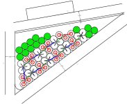
I did a quick layout of my battery in the bike frame and there is room for 14 more cells. Of course, I would have to disassemble the entire pack and reconnect in groups of 4 instead of 3.
batt 14s 4p.jpg
I did experiment with the simulator some but without information on my actual hubmotor or controller, it can't help me predict speed or power. It does demonstrate possible gains by changing to a higher current controller, if indeed that is the bottleneck in the system.
 
Are LiitoKala cells considered good quality?

I recall a "fake / counterfeiting" issue some while back?

My understanding it's worth paying a bit more for Sanyo/Panasonic, LG, Sony or Samsung.

Of course if saving half or more there might be genuine bargains out there. . ,
 
john61ct said:
Are LiitoKala cells considered good quality?

I recall a "fake / counterfeiting" issue some while back?

My understanding it's worth paying a bit more for Sanyo/Panasonic, LG, Sony or Samsung.

Of course if saving half or more there might be genuine bargains out there. . ,
There are lots of fake batteries out there. All of the reviews I have read on the LiitoKala cells were very positive. Several folks have tested and found them to be higher capacity than advertised and several have built very good ebike battery packs from them.
 
SYOTR said:
I have a home built ebike with rear 1000W hubmotor kit. The controller is an older, 48v no name ebay purchase with no current specs. Previous;y I powered it with two 12Ah 6s quadcopter batteries in series, about 44v nominal. Recently, I built a 15Ah 52v battery using (42) 26650 cells in 14s 3p arrangement The battery works fine, but I expected a bit more speed and torque. It tops out at about 30 mph and acceleration is not as quick as I had hoped. This is on a 26" mountain bike with a 150 lb rider.
I am wondering if changing to a higher current controller would help. Do I need to go to a higher wattage hub motor as well?

I didn't see you mention the before speed. For speed, if the before was 26 mph, then no, then more amps won't help. If the before was greater than 26mph, then yes more amps may help. if it was less than 26 mph, then that would be odd.

For acceleration and pulling power (e.g. uphill), more amps usually helps.
 
I looked at those cells before and considered them 10 amp max cells which I was fine with but fast charging them knocks the cycle life down 250 cycles so I took them off my list. if you look at the graphs you linked to you can see the volt sag. im not looking at your charts right now but I think at 10 amps they only delivered about 3500mah at 3.2v/lvc and 7amp was 4000mah, 20 amps was real bad. they weigh twice as much as an 18650, 98g I think so 2- 25r batteries is 5000mah and could easily deliver the 20 amps. the more you compare them the worse they look.

3p pack wheres your positive and negative wires coming off your pack, for example
negative at 1s1p? and positive 14s1p? I cant remember if you said how you paralleled the 1s and 14s parallel groups
 
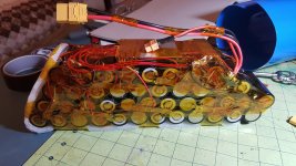
just a second, that picture of the battery. are you spot welding the 3 nickel parallel tabs together and then using 1 nickel plated copper for the serial connector from 1s to 2s and so on, if so that means the nickel strip is limiting the flow of amps wouldn't it?
 
SYOTR said:
I really don't have a way to measure the current or watts right now.
then it will be difficult to know if any controller you get is actually higher current than what you have now (except that when the voltage sags more, it's pretty likely that it's higher current draw from the battery). if it's physically larger, it's probably capable of higher current, though it may not be setup for it.

you don't have to get one, but wattmeters are relatively cheap, and useful for troubleshooting problems like you're having now, because you can directly compare one situation and setup with another.

for instance, you could test to see if your controller was maxed out at it's current limit when you are unable to go faster or whatever other problem you happen to have. if it was not maxed out at the time, then a higher current limit controller would not help fix that kind of problem. if it *was* maxed out, then a higher current limit controller would help; to what degree might be calculable by the info the wattmeter gives.


The cells I am using are LiitoKala INR26650-50A which should have a low resistance, Here are some tests of them which showed a calculated internal resistance of 0.04 ohms: http://budgetlightforum.com/node/56542

0.04ohms is 40milliohms (mohms).

so for your 14s 3p pack, that would be 40mohm per cell / 3p = 13mohm per group, 13mohm * 14s = 187mohm.


just to give you a comparison, my entire eig pack's actual resistance (as measured by the Cycle Analyst during use, at all states of charge from full down to empty) is only about 38 milliohm, less than just one of your cells. its also 14 cells in series--so each cell group (2p) is only 2.7 milliohm, so each cell is a bit more than a tenth of that 40mohm calculated internal resistance for the liitokala cells you've got. so it can deliver more of it's power to the controller, at a higher current, and waste less as heat inside the cells.

i'd have to go do a test to get exact numbers, but iirc at about 90amps (around 4kw) during the startup from a stop the trike draws at full throttle, i get something like 3v of sag at around half charge.

because they are much larger capacity cells (20ah each), and a different physical type (flat pouch), they're not directly comparable; this just shows you that internal resistance makes a difference in how the pack performs.

your rc lipo cells are probably similar (or even lower!) internal resistance to my eig cells, so they also would sag much less (at least, when new; as they age the resistance of any cell gets higher) than your present cells, and so give more power to the system and waste less as heat.


using some guesstimates:

if your controller's current limit is 20a, and the pack resistance is 0.187ohms, then 20 * 0.187 = 3.73v. since your sag is around 5v, then 5v / 0.187mohm = 26.7a.

so it's an educated guess that your controller's current limit is probably around 25 to 30a.


so...let's say it is 30a, and you get 5v of sag. that's 30 * 5 = 150 watts of heat generated inside the battery pack, distributed among the cells. might not seem like much, but a 150w incandescent light bulb is pretty danged hot; almost all that 150w the bulb uses is put out as heat. so this means your battery pack heats up inside quite a bit when run hard enough to sag by 5v. if you have long runs of that, the pack is probably getting a bit on the toasty side inside. if you're curious, you can monitor this temperature easily enough, with any kind of remote temperature sensor (indoor/outdoor thermometor, runnign the wire for the outdoor sensor inside the pack, or bbq grill thermometer with remote probe, etc).


the problem here is that if you run an even higher current controller (assuming the system needs more current to do what you want; you'd have to test that first **), the pack will get even hotter. let's say you get a 60a controller just for overkill. ;) there will be even more voltage sag; 60 * 0.187 = 11.2v of sag! meaning speed of the motor will drop significantly because it has less voltage to cause it to spin. then, that 11.2v * 60a = 672w of heat! that's more than four times the amount of heat generated at the lower 30a current. :shock:


so... internal resistance of a pack makes a difference to how well the whole bike runs.


the battery is the heart of the whole system, and if it can't supply the power needed, without much loss inside itself, the whole system runs worse than if it could.


keep in mind that all the above is *only* about the *cell* resistance, and hasn't taken into account any of the interconnects, like the serial nickel strip connections between groups, or the spot welds, etc., all of which *also* contribute even more resistance to the system, and waste even more power as heat.
 
goatman said:
just a second, that picture of the battery. are you spot welding the 3 nickel parallel tabs together and then using 1 nickel plated copper for the serial connector from 1s to 2s and so on, if so that means the nickel strip is limiting the flow of amps wouldn't it?
Each group of 3 in parallel are joined with the nickel strips which are welded to each cell. Then each of the series groups are joined with much heavier .3 mm x 8 mm nickel plated copper strips. See attached photo.battery.jpg
 
exactly, the nickel strip restricts the flow off high amps and if the nickel strip is plated steel that would restrict the flow more, I think ive read as low as 2.5 amps for nickel plated steel strips.

you are trying to pull amps from the battery to the nickel plated copper series connector, you could try doubling up the nickel strip but let someone else here reply, I could be wrong with my thinking.
 
goatman said:
exactly, the nickel strip restricts the flow off high amps and if the nickel strip is plated steel that would restrict the flow more, I think ive read as low as 2.5 amps for nickel plated steel strips.

you are trying to pull amps from the battery to the nickel plated copper series connector, you could try doubling up the nickel strip but let someone else here reply, I could be wrong with my thinking.

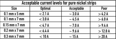
The strips welded to the cells are pure nickel. I did not measure them but assume they are sized to handle the rated current. I kept them are short as possible. I found this chart for sizing strips. nickel strips.jpg
I read that copper would handle 4 times the current of nickel strips. Based on that, my .3 x 8 nickel plated copper should be optimal for more than 40 A and acceptable for more than 60 A.
The size of wire that came on the speed controller would not carry this current and is much longer than the strips.
 
just by looking at your pack if the nickel looks like the same thickness as your nickel plated copper/ 0.3mm then according to your chart you should be fine but if its half as thick/0.15mm it cant take the amps. that's why I mentioned doubling up your nickel strip
 
Back
Top