Rohloff & other IGH at high power - measuring & limiting torque?

john61ct

1 TW
Joined
Dec 18, 2018
Messages
8,758
I believe wrt abiding a high torque power train, nothing beats the 14-gear Rohloff Speedhub at a 526% range, rated for 130 N.m

Please correct me if that's wrong, happy to hear about other non-derailer options like Shimano / Alfine, Sturmey Archer ? and others, maybe even DIY ?

I would like to verify through experimentation, which motors are well suited to couple with a Speedhub, so that their max torque is not **too** much higher than what the IGH can withstand,

intention is to use tuning to limit the mechanical power (via phase amps?) to just below the shear point,

e.g. with a cargo rig at 400+ lbs, standing start on a long steep hill.

I've learned that torque is not simply a matter of weight / slope and motor power, but depends a lot on ramp-up and other factors.

For example much more stringent limiting is required for throttle control, as opposed to PAS. I assume that outside of sophisticated FOC type controllers like Nucular, the CAv3 would be used for that limiting function.

My understanding is that the Rohloff design includes precisely engineered shear pins that act as "torque fuses", purposefully sacrificed in order to protect the expensive gearing inside.

Does anyone have an informed opinion on how fail-safe these would be, to allow for repeated destructive testing?

If breaking the pins is too risky a test method, is there another kit setup / tool that could be used to measure that torque at the IGH input in a way that would closely replicate it?

I am looking at the Lightning Rod "big block" vs XL models, other mid-drive suggestions most welcome.

Separate topic really.

If it turns out that more than 130 N.m is required for my use case, could one of those, as right-hand chain drive, be configured to "bypass" the IGH to power the rear wheel directly

and thus the Rohloff only powered by leg muscle energy and/or a second, lower power motor?

One of my base options is to start off with a strong steel tandem frame, so two BB-based motors might be possible?
 
Hi,
Will you apply the testing torque with a moving bicycle chain or a static 'torque wrench' mechanism ?
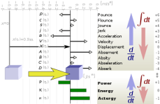
Because what I read here the chain acts like a sacrificial ' torque fuse link ' that pops upon sudden acceleration (jerk?).
Good luck
Mike
 

Attachments

  • Jerk.png
    Jerk.png
    11.6 KB · Views: 1,549
Standard cassette and derailleur have much, much more torque handling capacity and if it's the adjustment and maintenance of a derailleur that bothers you may I recommend an electronic auto adjusting derailleur. You can even shift under power with a cassette, good luck doing that with the geared hub.
 
john61ct said:
I believe wrt abiding a high torque power train, nothing beats the 14-gear Rohloff Speedhub at a 526% range, rated for 130 N.m


If it turns out that more than 130 N.m is required for my use case, could one of those, as right-hand chain drive, be configured to "bypass" the IGH to power the rear wheel directly

IGH are awesome planetary transmissions. That said,...

"526% range"....


Jesus 130Nm is very little for takeoff. Human level of power expected by the IGH manufacturers. An electric motor will overvcome that easily... especially reduced on a mechanical reduction ratio.... In an instant. Isnt the BBSHD 160nm? Even with a small reduction you are having a polar moment of tq higher than that if it is reduced even a tiny tiny bit.

That said, I honestly dont know what a cassette can take peak. I see them folded over from BBSHD tq all the time. ON the 34T? Ebikes usually take advantage of the Tq off the line and sell more drives that way. Elec motors make Tq of the line with the amps, we all know that. So we want to limit amps off the line to achieve a throttled torque as not to have the lurch break the IGH.... Once moving the IGH should be able to take it much better.. but... Ya know.. It will be a friggin dog. Geared that way.

Gearing electrical motors is a weird science. .... Where/how it makes its power, then does its work with that power. I do not begin to know it all.

"Free horsepower for acceleration " is the entire reason for a close ratio geartrain. 99.95% of bicycles are wide ratio ( divide the first ratio by the last.. if that number is higher, it is a wide ratio gearing.. . If that number is low, it is a close ratio gearing. ) If you have the Hp and accelerate, you are making a very well defined amount of tq....

Zx10R=
1st= 9.36:1
and
6th- 4.81:1...
so the gearing ratio is
9.36/4.18=

(2.23) (close, fast and slapping gears in the tourniquet range everytime, right where the engie makes the power, in that rpm range... where the Tq comes on... )

FatBoyHarley:
1st = 10.11:1
and
5th = 3.15:1... SO....
so the gearing ratio spread is =
10.110:1/ 3.150:1 =
(3.29) (slow, wide ratio, no HP, low top speed, and not enough power for another gear).. (but enough tq to start a log truck)

Like a truck vs a racecar: Each with the same exact engines: different ratios make the vehicle.... Racecar is close ratio, truck is wide ratio...

Cars and trucks?
Subaru WRX close ratio box:
1st gear: 3.083
6th gear: 0.825
Gearbox ratio spread: 3.73 CLOSE CAUSE IT LIVES IN HIGH RPM AND MUST SLAP GEAR DOGS FAST AT THESE SPEEDS OR IT LOST THE RALLY

Ford Truck 5speed manual:
1st gear: 5.27:1
5th gear: 0.76:1
Gearbox ratio spread: 6.93 WIDE CAUSE IT HAULS LOGS


Typical bicycle ratio: mountain 2 (10 speed) chain ring derailleur setup ,
38-24 1st gear, 1.58:1
11-36 10th gear, 0.305:1

1.58/0.305= Ratio spread: 5.108.. WIDE as HELL.


Multiply that by your final drive ratio and you see the Nm you put into the hub axle.... and the tire can take it, you will hurt the drivetrain. Double chains or MC chains and shit. The three R's.. Repeatability, reproducibility, and reliability.

Do you know the ratio spread for your Rohloff 526% tranny?

Maybe make it a high rpm close ratio.. but.... your first gear will be kinda wimpy. Put a big sprocket on the rear and a tiny sprocket on the front. Like a world record top speed bicycle... Tall.

Most bicycle ratio spreads are wide as hell is deep. Lol. Very wide ratio to distribute the (low) levels of human tq into something (power) usable for speed increase and holding.

If you want to throttle the tourque number to 130ftlbs peak expect to take off like a snail and have a long 1st gear. No real acceleration cause you will be bogged and loping up to the usable range of tq.

You could do it many many ways. All depend upon logical conditions and some feedback looping. Stress strain gauge. Accelerometer and closed PID loop. Gyro with Pitch control? RPM/sec. All that jazz. Like the wheelie control box that is made for ebikes.. that is what it does.. Controls calculated Tq output.. Rpm/sec.... with an accelerometer.. Sketch Coleman? Is developing it. I think that is the coolest and closest thing I heard about when it comes to active ebike tq control.

HP - Horsepower calculated from rate of speed change.
MPH\ Xxx\ Gear
- Inputs:
- "Tire Diameter(in.)" - Drive tire outside diameter in inches
- "Final Drive Ratio" - Axle drive ratio
- "Transmission gear ratio" - ratio for the transmission gear used

Hp Rpm
Calculated Tq
MPH/Gear
Speed MPH from RPM
Tq delta rate (change in Tq rate)
Thro delta rate ( change in throttle input (or output? IDk Im not a programmer I just ride bikes)
Delta Rpm
Accel hp
Instant Wh/Mi

Those things. Torque control (traction control) is used all the time on racecars and bikes, all software calculated and implemented from various feedbacks with "1970's Motorola microprocesser" level of sophistication. Tuned and tailored on the actual dyno.

For a spark ignition internal combustion engine you limit MEP through MBT calculations and retard spark. For an electrical motor I suppose you would look at MBT and retard amperage delivered. It doesnt look (measure empirically) at the actual traction...

...it looks at what it calculates for Tq, and decides to act upon those (well tuned hopefully) calculations, to "retard" the power (output).

Many look at the rpm/sec to know if the wheels are spinning ( or going to begin to spin)... at any second.. ( millisecond).. and then to throttle the output of the driven wheels. Traction control looks at a few inputs to detect when there is wheel spin, and then decides when it should reduce motor. HP and Tq exist to be calculated from empirical measurement... Since day 1,.. I would thing a algorithm to control torque on a ebike would be similar, software wise.

I have absolutely 0 (zero) experience with the management of tq, maximum brake torque, and or programmin well designed integrated semiconductor circuits with multiple ADC or DAC for desired operations. If anyone has any such input, be free to correct me.
 
You guys are tossing terms, examples numbers around as if I have a clue, I don't, noob 101 level please.

The Rohloff steps are evenly spaced about 13.5% each

A recent member described adding a Schlumpf Speed Drive at the BB, 1.65 overdrive version
to give the Rohloff a total range of 868% total gear range,

vs 636% for Pinion 18-gear.

If top speed ends up 12mph that's fine; if I need an 8kW motor that's fine too.

This use case is all about that 4-500lb load starting from dead stop pointing up a big steep mountain road, the real key will be a ssllloooooww ramp up,

small wheel of course

and even once getting going up that slope, wheels keeping to a slow speed but motor at high RPM.

_____
I don't want to discuss derailleur alternatives, please stick to the topic, as I said multiple motors is the option once the mid-drive + IGH prove insufficient.

Think of it as a thought experiment if that makes you more comfortable.
 
I am just describing the relationship of gears / power / work. How it applies to the limiting ( of tq) to not break the (IGH) hub. Classically, the 1:1 ratio is the strongest in the IGH. Underdrive is one mode and overdrive is the other ( in the acquisition of speed and acceleration, manipulation of tq to suit ). Between them is the 1:1.

Some thoughts: ( not mine, just pulled randomly from others who have asked similar questions)
"How any RPM make 1 hp?"
"RPMs do not produce horse power. A horse power (1 HP) is equal to 746 watts. I can have a huge 1000 horse power motor (746,000 watt motor) running at 100 RPM and I could have a 1/4 watt motor turning at 10,000 RPM."

"There is a relationship between power and RPM but to calculate this you need to know the motors tourqe curve, ie what tourqe it creates at a specific RPM.

Power is the rate of completing work (or applying torque) in a given amount of time. Mathematically, horsepower equals torque multiplied by rpm. H = T x rpm/5252, where H is horsepower, T is pound-feet, rpm is how fast the engine is spinning, and 5252 is a constant that makes the units work in this case."

1800 rpm makes 1 hp( horse power) at 3 ftlbs.

1 HP motor produces 1.5 (ftlb) of torque at 3600 rpm

We have a Tq figure that we cannot go over. (Rholoff 130ftlb input tq). We have a weight (of the ebike /rider/payload). We have a wheel diameter. ( lets say 24": for simplicity, 1 foot radius). We have a distance (desired), to reach a certain speed. You will trade this distance off for top speed, and visa versa, depending on gearing.

You now have everything you need to know exactly how many amps you need to limit your motor output so as not to go over the specified ( Rohloff input) limit of 130 Ftlbs. If you know the rated output and efficiency of your motor.
I think.

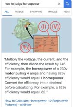
Hint: 1hp is 746 w.

There will be an acceleration in feet per second that if you go over this you will go over the 130ftlb max input of the hub and break it ... If you do not accelerate this fast you will not have this problem.. ( re: gearing down to go slow). Trade the RPM for tq. You will not use any power if you have next to zero top speed. How a small motor can move a big thing. Very slow. How this applies to out ebikes, is the same as any vehicle. How it is managed is up to the installations sophistication.

Most motors or engines are not made to start off in a 1:1 ratio. Mostly only pushmowers that are economical slow rpm air cooled engines. A DD hub motor. Sprint cars with 700 hp V8 straight to the diff... no transmission.. and 1400 lbs GVW, to accelerate the pair of 24" wide dirt slicks as fast as possible.... (a power-to-weight ratio besting that of contemporary F1 cars.) .. in a sprint. Most go karts use a 1:1 ratio too. Fast fast two stroke (DartKart GrandsPrix?), with a pair of Mac10s on a single axle and Goodyear racing slicks.(the good ol' style "push to start" Go Kart, no clutch, just sprocket(s) to the crank(s). Dont bog down, or stop, the motor will stall. Lol. )

All cars and trucks reduce rpm for more tq to begin the mass moving (1st gear, underdrive), ... go through the 1:1 ratio ( typically 4th gear),.,.. then overdrive the rpm ( in the last gear). The ratio spread is dependent on the application ( close or wide tranny, hauling logs uphill with an 18Sp Peterbuilt or racing a Ducati witha Kawasaki... or getting groceries in a minivan), and tq curve of the input power source.


Same as a IGH.

We can plug the numbers in to know exactly how fast ( accelerations) you have to output to reach a certain top speed, and not ever go over that 130Nm torque figure ( output from drive motor, input to the Rohloff) that is turning the crank sprocket teeth ( on a typical mid drive) based on the weight of the vehicle ( and the power of the motor). Wanna plug the numbers in? Since Grin added mid drives to the simulator ( ratios) , this is easy to visualize. We can model it easy with the choice of like 100 differnt motor profiles ( or any custom motor).. Like the 1hp 750w BBS02... See what gears you would have to choose to never go over the Rohloff 130Nm input figure... with the choice of cogs available ( both, the front, BBSO2 chainring and rear Rohloff cog(s), right there on the left of the graph in blue.)

You will have a top speed and a peak torque, to move your 400Lb cargo bike and the (M/Sec/Sec) acceleration this will give you. :) Grin Sim goes far, even takes wind and grade into consideration for the users, should the user choose...
 

Attachments

  • judge hp.jpg
    judge hp.jpg
    79.8 KB · Views: 1,503
I do **not** want to size a motor so its max peak output is not capable of breaking the IGH.

I want a motor that can output continuous power way higher than that

and then use controls to keep that output below the IGH breaking point.

So most of the time in normal use, the rig is only using say 20-40% of the power capacity

and in rare cases when extreme torque is required, using maybe 75-85%
 
And a theoretical model does help with initial design & selection of components.

But here I'm asking about howto do real life experimentation on the IGH with a given (overpowered) motor,

tweaking the control system (including maybe training muscle memory) so I am getting max torque, ramp up just shy of that breaking point.
 
john61ct said:
I do **not** want to size a motor so its max peak output is not capable of breaking the IGH.

I want a motor that can output continuous power way higher than that

and then use controls to keep that output below the IGH breaking point.

So most of the time in normal use, the rig is only using say 20-40% of the power capacity

and in rare cases when extreme torque is required, using maybe 75-85%

And a theoretical model does help with initial design & selection of components.

But here I'm asking about howto do real life experimentation on the IGH with a given (overpowered) motor,

tweaking the control system (including maybe training muscle memory) so I am getting max torque, ramp up just shy of that breaking point.

Thats traction control.

You need to know how much Tq is produced at any single time,.

.....for how the "traction" is "controlled", is by limiting tq (output) through calculation ... from the traction drive source ( engine, motor, handcrank, footcrank). Yes you can either whip the slaves slower or faster, to lift the anchor.... Or you can integrate a few inputs/oututs, into modern computer codes, to manage the output of your traction drive source, just push the traction control button. Boom. Tq limited.

Still fact is, if you feed the Rohloff enough to break it.. It will be broken. .. How much that is, exactly, in real life, who knows.. So if you gear your Cargo bike like a race car.. or a Kawasaki, (close) then limit the tq, to acceptable levels..

You may get fast end speed based on aerodynamics and whatnot.. , but the acceleration will suffer when limiting the power ( to acceptable work levels of 130ftlb of input tq).... done alot in vehicle design I would go so far as to say.

Or gear it like a Peterbuilt, (wide) and not expect high top speed, but have the reliable Tq to move the load with the 18 gears.. and not break stuff when Joe Trucker slams the clutch ( cept the passengers back, when his head hits the ceiling.. as the truck rocks straining against its load... lol). You will not go fast (loaded, at least, or unless you can outshift Joe, who goes through all 18 speeds like his mum taught him... at light speed and yelling "Yeehaw!" )... but... You wont stall on the hill on the railroad tracks.

They use torque sensors in engine/vehicle design all the time, when designing the ignition maps and fueling algorithms. Torque sensors are not only for ebikes, you know.

You could use a (extra) bottom bracket Torque sensor with a known dummy load to know the tourqe output of your drive at any time.. just calibrate it and drive it off the wheels.... just for the data of how much tq you are actively outputting.... (Rube Goldeberg) (Balls out, governor design used to limit speed in old engines with 60-ton flywheels before the semiconductor revolution) I bet... or you can calculate it from speed, RPM and acceleration. Like most OEM traction control.
 
DogDipstick said:
Still fact is, if you feed the Rohloff enough to break it.. It will be broken.
Not if the shear pins - purposefully designed to be a "physical torque fuse" - work as per my understanding.

What I am asking here, is if anyone knows if it is OK to keep breaking those pins over and over while tuning the drivetrain to stay below that breaking point.

Or if not, suggestions for actually measuring that level of torque otherwise.

> You could use a (extra) bottom bracket Torque sensor with a known dummy load to know the tourqe output of your drive at any time

I don't know the different types, but thought those were for measuring human pedal power?

With a Lightning Rod big block using a separate right-hand chain, the sensor would need to be at the hub right?
 
john61ct said:
> You could use a (extra) bottom bracket Torque sensor with a known dummy load to know the tourqe output of your drive at any time

I don't know the different types, but thought those were for measuring human pedal power?

Tq sensors measure ( shaft) Tq, not human pedal power. They only measure human pedal power if there is a human there, pedaling the crank attached to the measured square taper shaft, and the distances are known, and the sensor has been compared to a known calibration ( of ftlbs).

Everything that turns produces a torque, based on its mass and speed... ( rpm and hp, work constant). Driving the chain, or driven by a chain, the sensor will still measure the torque on its chain if the sensor is pointed the right way, and output a signal....( relative to the spinning mass, dummy load, on the Torque meter you are going to implement) and based on the calibrated load.. vs signal.. you now know the torque..... at any time.

Maybe. I would bet they would work either way.. driving, or being driven. Maybe someone could chip in to acknowledge whether this would work, IDK. I think it would. Give the user a nice 0-5v signal to work with that is in direct proportion to the tq produced by the vehicle at any time, given known constants.

You dont even need that. You just need a wheel speed sensor... and a clock.

Really cheapest and simplest way OEM do it.
 
john61ct said:
What I am asking here, is if anyone knows if it is OK to keep breaking those pins over and over while tuning the drivetrain to stay below that breaking point.

Or if not, suggestions for actually measuring that level of torque otherwise.
If you just want to know exactly how much torque the hub can take, you could use a torque wrench on the crank to apply a known torque. Keep increasing the setting until you shear the pin. Torque wrenches are usually calibrated to +/-3% accuracy.

Then you could set a phase current limit based on the motor Kt and gearing (minus some safety margin).

Of course that doesn't take into account pedal torque. But developing a closed loop system to measure real-time torque output (combined motor and human) and then limit motor torque, is complex.

The simpler way would be to adjust your riding style. If you're hard on the throttle, don't pedal hard. And vice versa. Make sure the safety margin mentioned above can accommodate some light pedalling on top of peak motor torque.
 
serious_sam said:
If you just want to know exactly how much torque the hub can take, you could use a torque wrench on the crank to apply a known torque.
I would assume the mfg spec is pretty close.

Looking to measure the torque **as produced** by my drivetrain, so I can tune the controller (or CAv3) to stay below that breakpoint.

> Then you could set a phase current limit based on the motor Kt and gearing (minus some safety margin).

No idea how that math would work, I've been assuming experimentation is required. I do need to push right up to the envelope to maximize torque at a certain low speed range - also TBD in that heavy/steep scenario.

> Of course that doesn't take into account pedal torque. But developing a closed loop system to measure real-time torque output (combined motor and human) and then limit motor torque, is complex.

Yes, hence my desire to do live testing, IRL with the actual rig.

But from my reading so far it seems that the way human power is applied, is much less of a problem, I may need to put all my weight on the pedal starting from a full stop pointing uphill, but I won't be jumping up and down on it :cool:

> The simpler way would be to adjust your riding style. If you're hard on the throttle, don't pedal hard. And vice versa. Make sure the safety margin mentioned above can accommodate some light pedalling on top of peak motor torque

I'm not worried about on the flat, or even once gaining some momentum, will be 50-80% less torque there than the target worst case scenario above.
 
The torque as produced by your drive train will be close to the the calculated torque using the motors Kt (torque/amp) and the amount of amps you are feeding it as set in your controller. These values are pretty reliable.

Also, you keep mentioning your NoobNess. If you are such a noob why are you so positive that you need every last drop of torque right up to the failure threshold. Seems like speculation and you are basing your entire build on that instead of using useful values. Have you tried playing around with the simulator on ebikes.ca? You can simulate your expected load, amperage, voltage, grade, wind resistance, speed, etc. It should give you a good idea of what similar size/weight motors are capable of.

My unscientific shooting from the hip estimate based on riding lots of ebikes is that an LR big block at 8kw geared for a max speed of 15mph could likely climb a 7% grade until the battery runs out. That's only a 1500-2000 watt continuous task with a 500lb bike.

There are lots of people on here that like nerding out with ebike math and will help you calculate the torque you can expect on the drivetrain. There are not many people on here that are going to advise you as to what is the best way to repeatedly shear the safety pins in your hub. There is likely not a good way to do that safely and reliably and I'm not sure there should be.
 
DanGT86 said:
Also, you keep mentioning your NoobNess
On topics where I know very little, like biking and physical mechanical stuff like motors and gearing, I want to make that clear, as opposed to for example certain types of batteries. Both apologizing in advance for "stupid questions", and ensuring those noobier than I do not make mistakes based on my misconceptions.

> The torque as produced by your drive train

Do you mean at the input to the Rohloff, or at its output, or where the tire meets the road?

I'm still unclear on this key (noob) question:

"is it OK to go up to a bigger tire size since I now have the IGH?"

_______
> why are you so positive that you need every last drop of torque right up to the failure threshold.

Because I need to carry as much weight as possible for the drivetrain's capabilities vs the slope of the road between the town and my campsite. Every extra gallon of water means fewer supply trips per month.

So, once I know I can load up X pounds and get back to camp over a given mountain pass, I will only fill that last 5-gallon container up to that point.

> My unscientific shooting from the hip estimate based on riding lots of ebikes is that an LR big block at 8kw geared for a max speed of 15mph could likely climb a 7% grade until the battery runs out. That's only a 1500-2000 watt continuous task with a 500lb bike

Sure, sounds great, but the point of this thread is, how can I ensure that doing so - maybe having to pause halfway then restart from a standstill - won't go over the max torque the IGH can withstand?

Obviously I do not want to shear the pins, even once if possible.

So what can I do to proactively prevent that,

or maybe just sound a loud buzzer, to signal that I'm approaching that point, whether from a stop, or accelerating from 5mph trying to get up to 8mph, or whatever?

 
DogDipstick said:
Jesus 130Nm is very little for takeoff. Human level of power expected by the IGH manufacturers. An electric motor will overvcome that easily...

That is input torque, not output. The direct drive gear is #11 of 14. In low gear, 130Nm at the rear sprocket becomes 466Nm at the wheel.

Rohloff specify a minimum input gear ratio of 2.4:1, or 38/16. If you use this gearing, and 175mm cranks, you’d have to push on the forward pedal with 400 pounds of force to reach the input torque limit.

Basically, you’ll only break the thing if you gear it wrong, with too much reduction on the input. But it has enough gearing range that theres no good reason to do that. You just add your maximum pedal torque to your maximum motor torque, and pick an input ratio that results in no more than 130Nm at the rear sprocket.
 
john61ct said:
Because I need to carry as much weight as possible for the drivetrain's capabilities vs the slope of the road between the town and my campsite. Every extra gallon of water means fewer supply trips per month.

I have used a Rohloff laced into a 26” wheel to carry 450 pounds gross weight up 20% and steeper grades many times, and I never got very close to the input torque limit. There’s enough gear range that you don’t have to push it like that.

if you need more than 450Nm at the wheel... you need a better plan.
 
You can figure the torque anywhere in the system with relatively basic math if you know the ratios and the diameter of your wheel. So my statement doesnt apply exclusively to the input or output of the IGH.

If you are worried about the input torque into the IGH then I would suggest you work backwards starting with the vehicle weight and the expected grade. This will give you the required force to simply do the lifting. From there you need to pick a tire diameter that you are willing to use. Using the tire diameter and the gear ratios of the hub you can figure out how much input torque is required to do the job and at what speed. If that resulting number is something way lower than your shear pin torque then you are on the right track. From there I would use one of the more advanced calculators online to factor in the effects of acceleration, tire drag, and wind resistance.

I guess an easier way to say it is that there is a specific speed that you can haul a specific load up a specific grade. That is determined by the maximum input torque of your IGH. Figure that out first and then it wont be hard to limit a motor not to exceed it. Any controller that is programmable will allow you to limit phase amps and ramp up speed. Some will require a CA3 and some will not. You do not need a complex torque monitoring device. If your life depends on it then put a mechanical limiter between the motor and the input of the hub like an overload clutch. I say that because if you life depends on it you aren't going to trust chinese hobby electronics anyway no matter how programmable they are.


To answer your tire size question: yes the diameter of the tire will have a significant impact on the input torque into the IGH and the output force at the wheel. It is like a gear ratio in itself. For instance a 20" wheel will give you the same output force to the road with only 77% of the input torque. Its radius is 77% that of the 26" tire. If you really think your required speed and acceleration is going to be close to the failure of those pins then use the smallest wheel you can stand.

My shoot from the hip estimate was to illustrate that you are not asking for something unreasonable in the ebike world. Based on experience I think you could go directly to the shell of the IGH bypassing the internal gears and using a high rpm motor like the LR you would have more than enough torque available to pull a 2000lb car up that hill if you weren't in a hurry.

If you are looking to make some ultra efficient featherweight vehicle with a tiny RC motor then you need the complexities of the IGH and tons of engineering to keep everything right at the point of failure. If you are OK with buying way to much motor like it seems you are then you can do way looser engineering and have way less points of failure.

Here are some simulators to play with
https://www.robotshop.com/community/blog/show/drive-motor-sizing-tool
https://vesc-project.com/calculators

Quick discussion with some formulas about figuring load required to drive up hill.
https://engineering.stackexchange.com/questions/6756/calculating-torque-needed-to-climb-a-graded-hill
 
Wow thanks, that is encouraging!

Balmorhea said:
That is input torque, not output. The direct drive gear is #11 of 14. In low gear, 130Nm at the rear sprocket becomes 466Nm at the wheel.
Is that just multiplying by the gearing ratio?

Keep meaning to slog through the sheldon pages to grok the math. . .

> Rohloff specify a minimum input gear ratio of 2.4:1, or 38/16.

So that has to do with the size of the big sprocket (belt pulley?) on the front, at the BB?

> Basically, you’ll only break the thing if you gear it wrong, with too much reduction on the input. But it has enough gearing range that theres no good reason to do that.

Exactly why I wanted that big range, also to still get some pedaling in too in case the electric side stops ten miles from home.

First time I heard about the Schlumpf overdrive too, 1.65 extra, gives the Rohloff **868%** total gear range!!


> You just add your maximum pedal torque to your maximum motor torque, and pick an input ratio that results in no more than 130Nm at the rear sprocket

You make it sound so straightforward :cool:

______
And does the first quote above translate to a "Yes" for this?
john61ct said:
"is it OK to go up to a bigger tire size since I now have the IGH?"


DanGT86 said:
You can figure the torque anywhere in the system with relatively basic math if you know the ratios and the diameter of your wheel
Great, i would actually pay someone, or donate to a charity whatever to get me past the 101-duh stage on this, also figuring out how to plug numbers into the simulators.

>If you are worried about the input torque into the IGH then I would suggest you work backwards starting with the vehicle weight and the expected grade.

Well, as I said, weight is "as much as possible"

qualifying now "with a cargo bike still possible to get moving on the flats under pedal power, and hoping I lose a couple stone getting exercise" :cool:.

So again, weight is **not** the fixed variable, that 125-127 N.m max torque input at the hub is.

> If that resulting number is something way lower than your shear pin torque then you are on the right track.

Not way below, just a **bit** lower to give a safety margin.


Maximum grade being say

"80% of the steepest grade encountered in the Eisenhower Military-Industrial Interstate System", probably Colorado somewhere.

> you need to pick a tire diameter that you are willing to use.

That resulting from a 26" bike rim +4" fattie would be ideal, settle for the 26" regular O.D. with say 3" tire allowing for a smaller rim.

I doubt if 20" would be OK when running over gullies and branches on forestry gravel tracks, that's why I'm hoping the Rohloff's 526% will allow for "regular" touring sizes.

Especially given that suspension may have to wait for version 2 of the frame. . .

> If you really think your required speed and acceleration is going to be close to the failure of those pins then use the smallest wheel you can stand

I do not care a whit about either of those factors, if the heavy load can just get up that tall mountain, with the Rohloff I think the rest will take care of itself.


> figure out how much input torque is required to do the job and at what speed.

The problem I still think will be the **low** speeds required to still keep climbing with all that (ever more added) weight, thus requiring moar torque.

> factor in the effects of acceleration, tire drag, and wind resistance.

I don't think they pertain to this thread's specific topic, tabled for now anyway, will revisit when figuring out how many kWh of lithium I need to lug around per distance back to camp :cool:

> Any controller that is programmable will allow you to limit phase amps and ramp up speed.

Well I understood that phase amps alone is only loosely ratio'd to physical torque, lugging uphill at 3mph being radically different from a zippy 8 or 10mph.

> You do not need a complex torque monitoring device. If your life depends on it

Obviously I will do my best to prevent that situation, but reliability / longevity **are** top priority in selecting components, thus investing in the Rohloff rather than trying to use a Sturmey Archer.

> a mechanical limiter between the motor and the input of the hub like an overload clutch

Aha! new term for me to google, I at least want to learn more about options like that, and also which controllers implement that "ramp up speed" feature best.

> you aren't going to trust chinese hobby electronics anyway no matter how programmable they are.

or at least carry spares :cool:


> Based on experience I think you could go directly to the shell of the IGH bypassing the internal gears and using a high rpm motor like the LR you would have more than enough torque available to pull a 2000lb car up that hill if you weren't in a hurry.

Sounds more complicated, but hence this thread, https://endless-sphere.com/forums/viewtopic.php?t=105857

> If you are looking to make some ultra efficient featherweight vehicle with a tiny RC motor

No.

> If you are OK with buying way too much motor

> you are not asking for something unreasonable in the ebike world

yay! Add another full 5gal container of water until I'm pushing the limits

:cool:

But seriously, every drivetrain will have its weakest link. In this case I plan for that to be the Rohloff IGH, and

that happens to be a **very** expensive point of failure, thus my caution, and maybe over-thinking.

Thanks so much for your helping me learn!
 
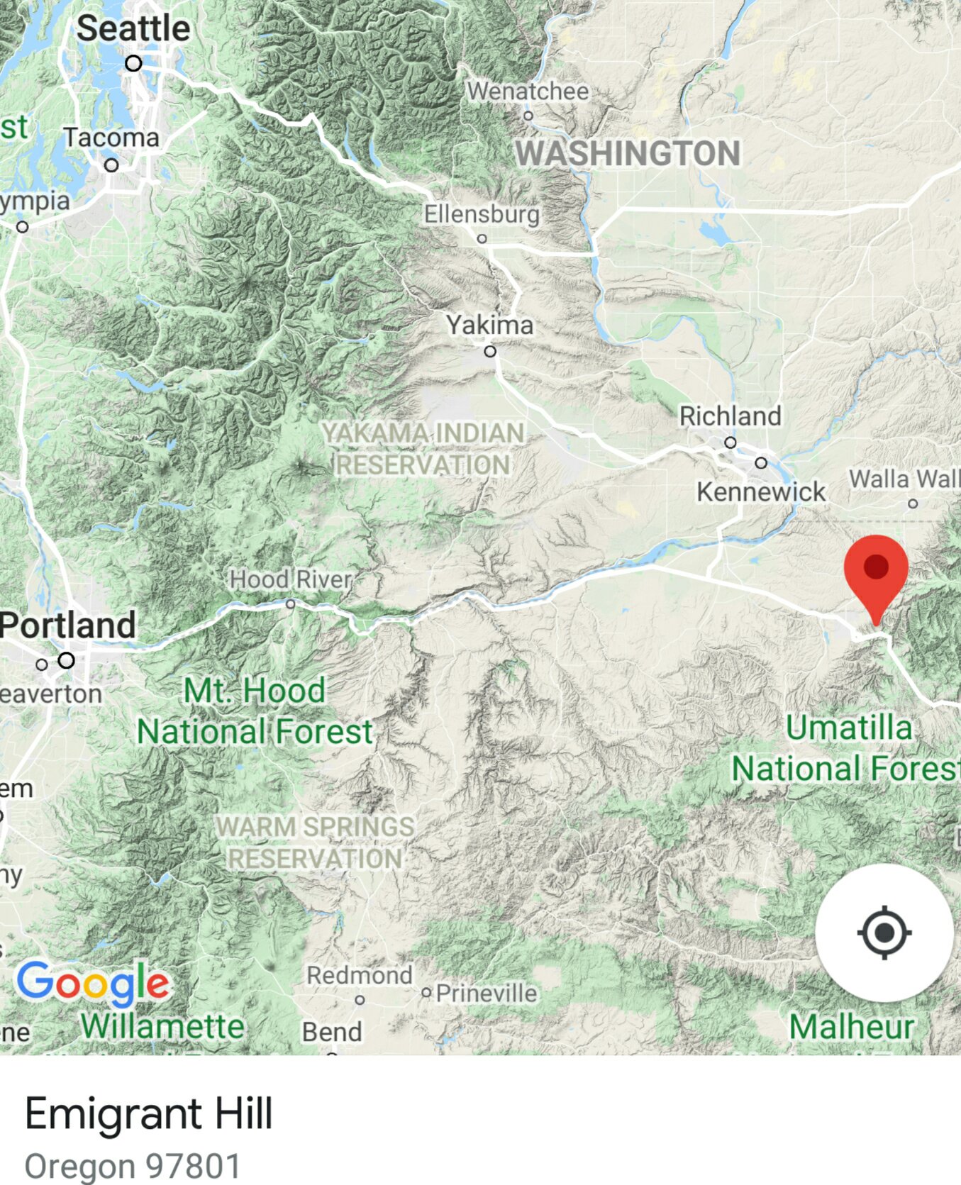
Emigrant Hill on I-84, just east of Pendleton OR is only 6% !

59e192e6ce0403e6b4875b0d83e802d4.jpg


_____
So given I'll be on much smaller tributaries, would 8% be unrealistically ambitious?
 
I did it the lazy way and used the calculator for robots that I linked in my last post. Here is what I came up with.

860lbs
26" wheel
10mph
8% grade
Speed 11 of the Rolhof which is 1:1
That would require an input torque of 129.56Nm. That is leaving no wiggle room for bursts during acceleration.

Surprisingly it would only be 1674watts of continuous power and would only require an 18.6 AH 72v battery to do that for 50 min. That is actually pretty impressive to me. Its a 3800 foot elevation change over 50min hauling 860lbs! Ebikes are cool. 1674 watts of actual continuous output is quite a bit more than most of us put motors through but its not outside the realm of possibility if you let the motor spin fast. A fan would go a long way in an application like this.

Speeds 12 13 and 14 are all gear reductions so they allow you some room for acceleration.

The same stats as before but using speed 14 makes your wheel effectively 17" which takes some torque load off your input gear and gives you wiggle room for acceleration.

In speed 14 if you are willing to accelerate to 10mph over 14 seconds you can do the same job without exceeding 130Nm into your Rolhof.

860lbs and 8% grade are pretty extreme so if you base your expectations on that then you will be pleasantly surprised with the durability under the majority of circumstances.

As for bypassing the Rolhof. Its not that complicated. You just attach a sprocket on the outer shell. For instance the disk brake flange on the left. Run a LR motor with a tiny sprocket on the motor and a giant sprocket at the wheel and you are good to go. No sending torque through fragile bike parts that were never designed for it.

Hopefully those numbers can help you grasp the concepts a little better.

Side note, that region from your maps screenshot is the most beautiful place in the US that I have seen yet. Some good friends of ours got married under the Bridge of the Gods in the Columbia river gorge and they just bought a house with river access on their property in WA. I might just have to come out and test ride this rig you are building.
 
john61ct said:
Balmorhea said:
In low gear, 130Nm at the rear sprocket becomes 466Nm at the wheel.
Is that just multiplying by the gearing ratio?

Yes. The low ratio of the Rohloff is .279.

Yes, you can use a fatter tire.

You don't climb long hills in 1:1 gear ratio. If you do, don't waste your money on a Rohloff Speedhub.

To calculate your maximum pedal torque, assume your whole body weight (in newtons) on the end of your crank arm (usually 0.175m). Add +50% if you are likely to pull hard on the handlebars to pedal harder in a standing position. Most of us here probably don't.

A 180 pound man weighs about 800N. 800N * .175m crank = 140Nm.
Let's assume he's got a BBSHD with 44t stock chainring.
140Nm ÷ (44/16 gear ratio) = 51Nm.
That gives 79Nm of motor that you can add with a mid drive, at the hub. It's still subject to the gear ratio you use to get it there.

BBSHD is claimed to deliver 150nm of torque.
150Nm ÷ (44/16 gear ratio) = 55Nm.

You see that this 180 pound man and a BBSHD both pedaling their hearts out together are hypothetically good for up to 106 Nm. That's 380Nm of wheel torque in the Rohloff's low gear.
 
Back
Top